44767
Statesman
 
Posts: 538
|
Post by 44767 on Nov 24, 2013 11:07:33 GMT
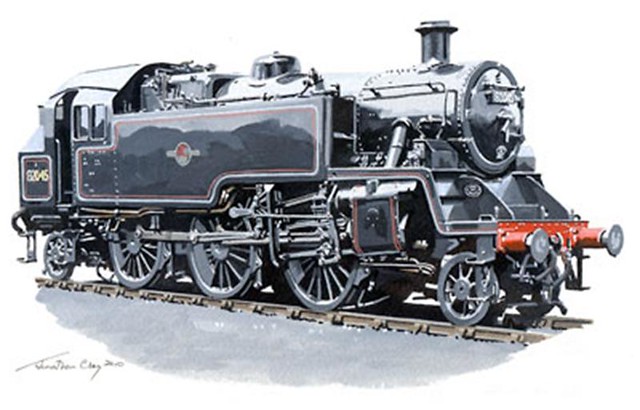 From a painting by Jonathan Clay I have been working on this project for about three years now and as I have started with the actual parts I thought I'd start this thread to show progress. It's funny how things came about. I was sorting out boxes of old books and I found my copy of "The Ladybird Book of British Railway Locomotives" It fell open at the page showing the class 3 tank (which was my first Triang-Hornby engine) and I wondered why one doesn't see live steam models of this locomotive. A search on the internet revealed that none was preserved which explains why- no one can photograph or measure the full size to design a model. At the same time I found a site for the new-build 82045. I immediately thought that if they're building a new locomotive they also must have the drawings. I contacted them to ask if it were possible to use their drawings but they told me that the drawings were copyrighted and they didn't want to get offside with the NRM. I had a similar response from the BRSLOG (British Railway Standard Locomotive Owners Group) even though I explained how I would be able to help the 82045 group to earn funds for their build. I therefore took it on myself to purchase copies of the drawings from the NRM. The first ones were general arrangements of the whole locomotive, the frames, the boiler and the motion. These then had drawing numbers for the individual parts and so made it easier to order the ones I needed. To date I have purchased about 200 drawings so this should be a very true to prototype model. My aim is to produce an accurate model in 5" gauge and eventually to provide drawings, castings and laser cut components to anyone who may want to build this model himself. I want the drawings to be 100% accurate and so I am building a batch of them to prove that the drawings are correct. I am designing the model in metric using a scale of 27mm = 1'. Drawings will be available in an electronic format which will allow the purchaser to measure anything on the model, cross-section parts or assemblies etc. I would like to have one part per drawing and a fabrication drawing as a separate drawing which should save the builder time. This image shows where I'm up to with the CAD model 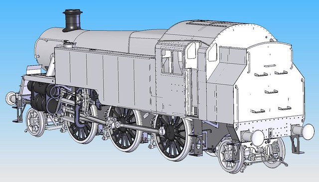 I hope this is of interest to some of you. There will be many things done a bit differently and I'll be making use of modern techniques and available resources to make this model. Mike |
|
|
|
Post by ejparrott on Nov 24, 2013 12:34:04 GMT
Look forward to seeing how you progress and I wish you all the best in your endeavours to market it, its something I keep pondering with my Manning Wardle. The seperate fabrication drawing is something I'm used to, usually as a set of stages which the designer has previously worked out is the best or in some cases only way of assembling the part.
|
|
|
|
Post by Rex Hanman on Nov 24, 2013 17:18:35 GMT
I too wish you all the best with this project. I have a long long way to go with my GWR large prairie but if I ever finish it maybe this could be my next project!
|
|
bhk
Part of the e-furniture

Posts: 458 
|
Post by bhk on Nov 24, 2013 23:22:55 GMT
Hi mike,
Really looking forwards to following the thread, will have to catch up again sometime when work settles down as you may have seen in the news things are a bit difficult at the moment.
Cheers
Sean
|
|
44767
Statesman
 
Posts: 538
|
Post by 44767 on Nov 25, 2013 3:54:45 GMT
Hi Rex, Thanks for your encouragement. If you're serious about building this then keep the flanging plates for the boiler you're doing. BR used the Swindon No. 2 boiler, shortened slightly and with a dome for the BR Class 3. All the original flanging plates were utilised. Sean, It'd be good to catch up again. You received a bit of a hospital pass didn't you? I hope it's not too bad trying to get the ship sailing again! Now just to get the show on the road... here's the first casting produced for the model. It's the main driving axlebox horn guide. Having modelled it in CAD, the stl file was sent to Shapeways and eight days later the rapid prototype arrived on my doorstep. This is the screen image of the stl file 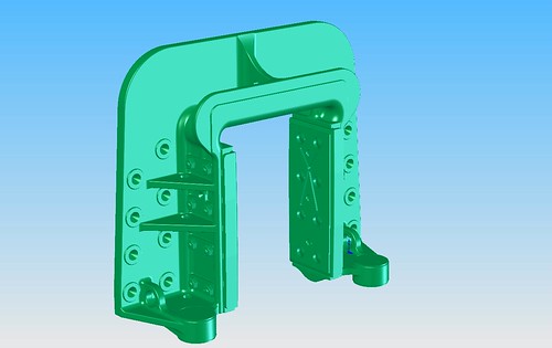 Note that the main casting, the manganese steel liners and their backing plates along with the studs and nuts which hold them in place, have been included in the same casting. I felt it unnsecessary to have them as separate pieces in this scale. Machining allowance was added where required and the file was scaled to take in to account the shrinkage expected. This was worked out using a test casitng (not this one) and measuring how much smaller it was than the original. Remember this takes care of any shrinkage in the rubber mould, the wax moulding and the casting. I found it to be a factor of 1.031. This is the first casting done: 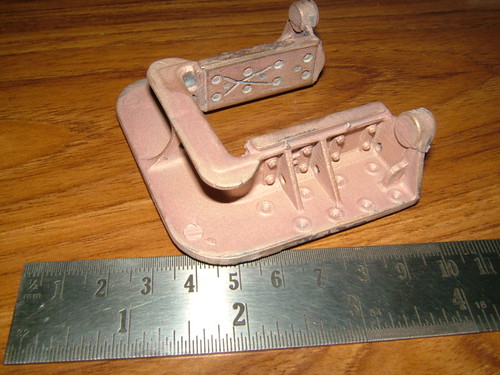 I have been making fixtures for the different machining operations. It makes multiple parts so much easier to replicate. With careful planning the fixture may be useful for other operations on the same part. Here's the first operation- machining the mounting faces and working faces of the cheeks. 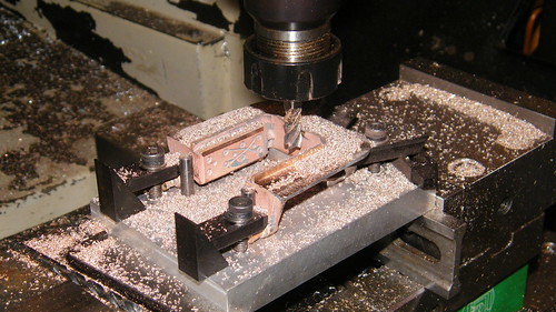 And the last operation, boring the cross stay holes. This fixture uses the register which will locate the guide in the frames to position the part for machining. The rivet holes were drilled through from dimples in the casting and will be used as a drilling jig for the frames. I don't particularly like doing this but it gets around the problem of shrinkage should my theoretical factor not be correct. 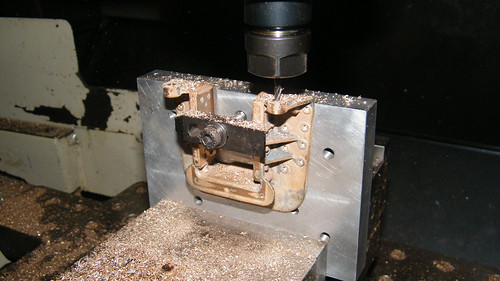 And here's the batch done ready to mount on the frames later 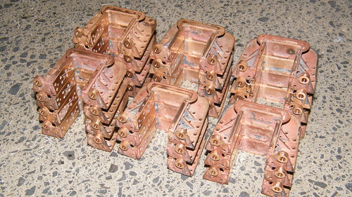 How's that for a start? |
|
|
|
Post by Deleted on Nov 25, 2013 10:46:30 GMT
Hi Mike I'd say that's a great start, I too will be following your progress closely.. I love the extra detail of the manganese steel liners but then I would..  great work.. I look forward to continued updates... Regards Pete |
|
|
|
Post by Rex Hanman on Nov 25, 2013 10:56:18 GMT
If you're serious about building this then keep the flanging plates for the boiler you're doing. BR used the Swindon No. 2 boiler, shortened slightly and with a dome for the BR Class 3. All the original flanging plates were utilised. Good advice but my prairie is in 7 1/4" gauge. However I do have a lovely class 2 78xxx in 5" that would make nice stable mate.  ( I didn't build the class 2) |
|
44767
Statesman
 
Posts: 538
|
Post by 44767 on Nov 25, 2013 11:01:41 GMT
Cheers Pete,
It's good to know there are a few interested. I'm hoping to get someone building one in parallel with me to give me feed back as I progress. At the moment I just have to check (and recheck) my own work.
|
|
44767
Statesman
 
Posts: 538
|
Post by 44767 on Nov 25, 2013 11:04:14 GMT
Rex,
Well I have already been asked if I would do a 7¼" version. Now that the design is well on the way it won't be too hard to scale it.
Mike
|
|
|
|
Post by Rex Hanman on Nov 25, 2013 13:23:42 GMT
Now you're talking!  |
|
|
|
Post by Deleted on Nov 25, 2013 13:26:45 GMT
WoW!---------now that's the way to do it....Those Manganese Bronze liners in full size are a bitch to machine in situ..The guys at SVR (Bridgnorth) constructed a "Bolt-on" grinding attachment that did the job...(LMS Black 5...either 45110 or 5000, whichever was the Whitworth-build loco)...and they do look just like that....Will continue to follow your v. interesting thread------
|
|
|
|
Post by Jim on Nov 25, 2013 23:48:10 GMT
Simply awesome work Mike. I look forward with more than a passing interest in following this build.  Jim |
|
44767
Statesman
 
Posts: 538
|
Post by 44767 on Nov 26, 2013 6:57:32 GMT
It's good to hear from you again Jim and glad that you're back in the saddle, so to speak. I've (well, the builders have) been rebuilding my entire garage/workshop. That has taken me out of action for the last year. Now there is all the painting to do- inside and outside. Anyway I now have a workshop/ garage/ office/ bathroom bigger than the rest of my house and it's only five steps up to the kitchen and the original part of the house!
The place I work for was bought out by a Chinese company so all the work we do now is for China which means numerous production line installation trips. I have one coming up just before Christmas and will be away almost all of January and February next year.
All I can do on the model is to take a roll of works drawings with me and work on the CAD side of things in the evenings. At least then I'm not wasting too much time but I really miss not being in the workshop especially as I have started making parts.
Mike
|
|
bhk
Part of the e-furniture

Posts: 458 
|
Post by bhk on Nov 26, 2013 9:37:51 GMT
Sean, It'd be good to catch up again. You received a bit of a hospital pass didn't you? I hope it's not too bad trying to get the ship sailing again! Cheers Mike, Once we get the propeller back from the seabed and they finish up there investigation we should at least be able to sail for dry-dock, most likely be away January to April with her. All depends on the regulators who are being very cautious. quite impressive to see a 300mm shaft sheared! |
|
|
|
Post by ejparrott on Nov 26, 2013 10:58:48 GMT
I'm intrigued....
|
|
44767
Statesman
 
Posts: 538
|
Post by 44767 on Nov 26, 2013 11:22:03 GMT
One of our interisland ferries which take passengers, cars, trucks and I think still, rail wagons, lost a propeller a week or so ago during a crossing on Cook's Strait. Sean works as an engineer on the ferries!
|
|
|
|
Post by Deleted on Nov 26, 2013 11:30:30 GMT
Hello all---------- had a fluid flywheel go walkabout from a diesel multiple unit whilst departing Paddington Station a few years back, that was "fun" but a 300mm shaft (12" approx ? )----that's impressive !!...Was it inboard or outboard of the plumber block (Thrust bearing) ??...(Professional interest = Ex.RN Engine Room Artificer)------------regards, Alan R
|
|
|
|
Post by Deleted on Nov 26, 2013 11:32:56 GMT
The place I work for was bought out by a Chinese company so all the work we do now is for China which means numerous production line installation trips. I have one coming up just before Christmas and will be away almost all of January and February next year. Mike -----------------------------CHINA, fast becoming the new America, in terms of Economy, trading etc... |
|
44767
Statesman
 
Posts: 538
|
Post by 44767 on Nov 26, 2013 11:43:26 GMT
Was it inboard or outboard of the plumber block (Thrust bearing) ??...(Professional interest = Ex.RN Engine Room Artificer)------------regards, Alan R I'm not sure Alan but they have found the propeller on the sea bed so I imagine the fracture was outside the hull Mike |
|
|
|
Post by Deleted on Nov 26, 2013 13:57:08 GMT
Ok, -----but I bet that gave the Engine Room staff a good, cardiovascular work-out ??... not to mention a Sphincter "twitch" or two, LoL !!!---------ps, Sorry, I meant to put STERN GLAND rather than Plumber Block.....Sounds like they were extremely lucky not to have taken on-board some of the wet stuff then ??--------------Of course it's the weakest point on any submarine as well, so how long before we see "smart" torpedoes with digital cameras that can do their final approach based on visual detection of rotating propellers ??-----------Finally, this is so obvious but I just couldn't resist it anyway. ENJOY >>>>>>>>>>>>>>>>> www.youtube.com/watch?v=8kNwvIEQsg0 --------------------- |
|


