bhk
Part of the e-furniture

Posts: 458 
|
Post by bhk on Nov 26, 2013 18:13:51 GMT
As mike says, we still take rail freight, one of the few left in the world. The shaft "snapped" Outboard of the stern seal, I can't say too much more at the moment and don't want to hijack Mikes thread.
|
|
44767
Statesman
 
Posts: 538
|
Post by 44767 on Nov 28, 2013 10:24:13 GMT
The first fabrication I tackled was the smokebox saddle. It is quite a complicated part to make so I was trying to decide what is the easiest way to make it straight forward for anyone to make. The full size drawing has a list of all the plates required to make the fabrication so I followed this approach- even naming the plates to same. I therefore made individual part drawings for each of the plates which are quite clearly dimensioned on the full size drawing. Using these individual parts I assembled them into an assembly. This then became the fabrication and I created a drawing from this file to show all those details. Now this becomes the "material" for the machined part. What I did next probably isn't the best way since it loses its parametric relationship, but I saved the assembly as a "part" and then started adding the machining detail to it i.e. all the machined faces, tapped holes and clearance holes for its mounting in the frames and for the cylinder mounting. This is the fabrication drawing. The dimensions aren't included as the drawings will be delivered in a format which will allow the builder to measure anything he chooses to. The last page is the page which would be saved as a dxf which gets sent to the laser cutters. Note that there have already been two revisions. The first was because I had designed all the slots and tabs to suit 1.5mm material. I thought, for some reason, that that was a standard size. If it is the supplier didn't have it so they made all the parts out of 1.6mm sheet. Of course none of the tabs then fit the slots! Luckily it was a one of set to prove it all fit together. The other revision was to add location tabs to the rolled saddle so it made it easier to align and so I didn't put it on the wrong way around! 3825003a____smokebox_saddle.PDF (188.72 KB) You will notice that the smokebox saddle fabrication includes the blast pipe. This was a separate welded steel part itself welded into the fabrication. I decided to make this close to prototype but by using a lost wax casting. The first idea was to make a core from a soluble wax which would be inserted into a silicon mould made of the outer shell and the core (extended to create core prints). Then the normal wax would be injected around the core in the mould which would make a seemless wax. The soluble core is then dissolved in an acid to leave the hollow wax. So I had rapid prototype made of the core and of the outer shell which was split into three pieces. One mould could be made of the core only and the other made of the whole lot. This is the CAD model of it.  The rapid prototypes for this:  Although this all looked like it would work, it was a bit more difficult that we thought. Abby (also on this forum) may be able to explain why. So the casting was redesigned into two separate waxes made in individual moulds which would be welded together. This is the resultant casting: 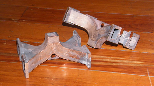 Along with the laser cut parts: 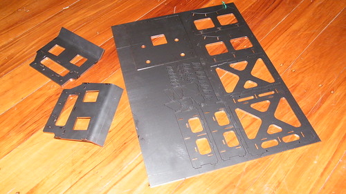 And machining the blast pipe: 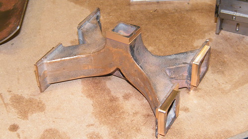 We get the fabrication ready for soldering together: 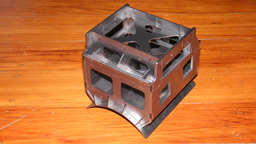 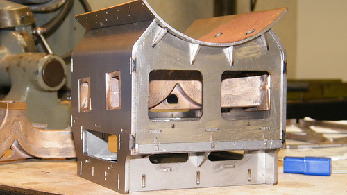 The next step is to machine them to the machine drawing. I am designing the fabrications so that there is machining allowance on the fabrication and any holes which need to align with other parts are machined in- they are not included in the laser cutting. It would be asking too much to get folding in exactly the right place for holes to line up with the mating part. Are you still follwing?! I think that's enough for now. Mike |
|
|
|
Post by Deleted on Nov 28, 2013 10:44:51 GMT
That's very impressive Mike.. I love the look of this piece..
Pete
|
|
jma1009
Elder Statesman
  
Posts: 5,917
|
Post by jma1009 on Nov 28, 2013 10:52:53 GMT
absolutely amazing and very very impressive!
quite incredible. im almost lost for superlatives!
cheers,
julian
|
|
|
|
Post by Laurie_B on Nov 28, 2013 10:52:58 GMT
Hello Mike.
This looks a fascinating and very well researched project.I have rather too many other projects on at the moment to start another,but maybe in the future!
Good luck with this,and keep us posted as the build develops.
|
|
|
|
Post by Deleted on Nov 28, 2013 12:10:02 GMT
Now THAT's how modern technology and Model Engineering make for good bedfellows IMHO !!!.....I know absolutely nothing of HOW it's done ( but then I don't know how to grow the tree that supplies the wood for my hammer stale)... However I do have an increasing awareness of what this "tool" called CAD is capable of.....which impacts on my thinking/planning for the production of my models etc......................... SO, I require some unique, 1-off castings for my 5" BEAR... I have the Engineering Drawings already produced.... who do I contact to get them made ?? ( Iron or Bronze)---- I already use Malcolm High's excellent cutting services at Model Engineer's Laser but have no leads for these brackets which------surprise, surprise, are NOT of a GWR standard type..... Can anyone help me ??-------------Mike, Sorry for the slight Hi-Jack. Hope you don't mind ??
|
|
|
|
Post by 3405jimmy on Nov 28, 2013 16:05:42 GMT
If your time poor and the drawings are in 3D and there one offs rapid prototypes in wax would be favourite. It’s not cheap but 5g is hardly going to be that big, which will keep the cost down. I would forget iron as getting something investment cast in iron is big bucks due to most people who do it being midsized companies, at least I have not found a cost effective on yet.
Richard at Abbey castings can get the waxes for you and also cast the parts in whatever bronze formulation you need. links are on my web site under links>modelling services.
Jim
|
|
Myford Matt
Statesman
  There are two ways to run a railway, the Great Western way, and the wrong way.
Posts: 621
|
Post by Myford Matt on Nov 28, 2013 16:47:49 GMT
Very impressive work, I do hope you continue to document this project in detail.
|
|
44767
Statesman
 
Posts: 538
|
Post by 44767 on Nov 28, 2013 17:40:11 GMT
Now THAT's how modern technology and Model Engineering make for good bedfellows IMHO !!!.....I know absolutely nothing of HOW it's done ( but then I don't know how to grow the tree that supplies the wood for my hammer stale)... However I do have an increasing awareness of what this "tool" called CAD is capable of.....which impacts on my thinking/planning for the production of my models etc......................... SO, I require some unique, 1-off castings for my 5" BEAR... I have the Engineering Drawings already produced.... who do I contact to get them made ?? ( Iron or Bronze)---- I already use Malcolm High's excellent cutting services at Model Engineer's Laser but have no leads for these brackets which------surprise, surprise, are NOT of a GWR standard type..... Can anyone help me ??-------------Mike, Sorry for the slight Hi-Jack. Hope you don't mind ? Discussion like this is welcome. I really want to have model engineers understand or be aware of what new technologies can do for us. What better way than catalogue a new design using such techniques. For one-off complicated castings, as has been said, 3D printing straight to wax would be the way to go. You'll need to find someone to create a 3D model of it which will be used to create the necessary .stl flie. It is expensive becasuse the machines are very expensive and the process is slow but the resolution is incredible. The jewelery industry uses this method increasingly instead of carving the waxes by hand. Mike |
|
|
|
Post by Shawki Shlemon on Nov 29, 2013 5:47:48 GMT
Very impressive and informative too . keep up the postings .
|
|
|
|
Post by Deleted on Nov 29, 2013 12:18:04 GMT
|
|
44767
Statesman
 
Posts: 538
|
Post by 44767 on Dec 6, 2013 6:57:19 GMT
I have had a week doing not much in the workshop but I've been preparing the next set of parts for laser cutting. It was quite obvious from the first set of stretcher parts I sent that keeping track of all the individual parts from individual drawings was a time consuming job for the sheet metal engineers. It was suggested that I separate all the parts by material thickness and by folded or flat and put all like parts on one dxf file. Also if a part is required multiple times then that is duplicated as required on the same sheet. This then allows the cutters to cut the ten off of each dxf of each thickness I need which in turn gives me the total number I require for all the models I'm building. I have left the individual part drawing as it was as this can be used by a builder who would prefer to cut his own by traditional historical methods. The beauty of parametric 3D software is that since these drawings are generated by the part model they will update automatically if a change is made to the part. As an illustration of this, I found that there were some holes in some plates which really were too small to be laser cut and probably were going to be tapped anyway so I opened the part model, suppressed the holes in the "fabrication" configuration and when I tabbed back to the laser cutting sheet the hole had vanished! That is the sort of thing which will not happen in AutoCAD. This is the sort of file so far. The main point to observe for a dxf when sending a part for laser cutting is to make it at a scale of 1:1 . It doesn't matter if it ends up in a tiny corner of the drawing page or is the size of your workshop it must be 1:1 scale for all views. frame parts for laser cutting stretchers on....PDF (61.11 KB) There are a few more parts to add to this but as the title suggests, this is all the parts 1.6mm thick which remain flat for the stretchers and brackets for the frames. Similar ones will be done for the 2mm, 2.5mm and 3mm parts and again similar for these thicknesses which get folded too. Mike |
|
|
|
Post by Jim on Dec 8, 2013 0:20:03 GMT
Julian's comment about being lost for superlatives pretty well sums it up. Mike is showing us a whole new world of possibilities and while it's way beyond my capabilities I've found much to make me lift my sights higher in what I want to achieve with my own models. If you get a chance, have a look at Mike's BSK, it's stunning, not sure if there are photos on the site, read broad hint.  Thanks Mike and please keep us posted. Jim |
|
44767
Statesman
 
Posts: 538
|
Post by 44767 on Dec 8, 2013 2:20:51 GMT
Jim, thanks, too kind. I'm not up to the standard of most on this forum but I am trying to be! this is a thread from when I first joined the forum which shows my Black 5 and the BSK. Not much has happened with the Black 5 although it now has passed its hydraulic test. |
|
44767
Statesman
 
Posts: 538
|
Post by 44767 on Dec 8, 2013 6:36:30 GMT
Now that Jim has mentioned it and I can take a hint here is my set of photos for my BSK M34015 . It was built from a Doug Hewson kit of parts but much research went in to getting some details corrected and adding in much more than was on the drawings. All the brake rodding is there which works when the handle in the guard's compartment is turned. Extra verticle stays were added to the underframe and heavier looking springs made for the bogies. The frames for the steps and battery boxes were actually fabricated from scale angle iron! It would be nice to se it hauled by my Black 5 one day.
Mike |
|
|
|
Post by Jim on Dec 8, 2013 7:39:07 GMT
Thanks Mike I've bookmarked the link for future reference for when I get round to my SK and Full Brake.
Jim
|
|
44767
Statesman
 
Posts: 538
|
Post by 44767 on Feb 2, 2014 5:58:37 GMT
There is an interesting development in the 12" to the foot scale. I have just found out about another new-build. It's the tender version of the class 3MT. There are quite a few identicle parts (including smokebox, saddle and boiler as well as all the valve gear, rods, wheels, horn gudes and motion brackets) to the tank version so it has got me wondering if I ought to do that version too. What do you all think?
|
|
|
|
Post by runner42 on Feb 2, 2014 7:15:01 GMT
Hi Mike, a bit of self deprecation. I am way down the list in terms of ME ability so my opinion may not carry the same weight as more experienced locomotive builders but. I think that a tender version would be an improvement and introduce the more classical lines found in British locomotives. Personally I think that it would be a more interesting project and would be good to compare the tender version with the tank version, particulary the changes to the cab area. However given your workload, you should guard against taking on too much so that the end date of this very interesting project is further delayed. Perhaps if you did a CAD 3D representation of the tender version you may able to judge for yourself the extra time involved.
Whatever you decide you have a captive audience in monitoring your progess.
Brian
|
|
uuu
Elder Statesman
   your message here...
Posts: 2,856
|
Post by uuu on Feb 2, 2014 9:19:08 GMT
A tender loco is like an old man pushing a shopping trolley. Real men have pockets or a Rucksack.
|
|
|
|
Post by ejparrott on Feb 2, 2014 9:22:26 GMT
See I think the tank version is a better proposition, takes less room to store and transport, and that seems to be a big issue with getting people in to the hobby. People do seem to be driving smalle cars now, the extra mass of the tender may make it less attractive.
Do both!
|
|