44767
Statesman
 
Posts: 538
|
Post by 44767 on Jan 20, 2015 6:50:06 GMT
What would be the damage on a pair of axleboxes Mike? To the UK obviosuly! I think a fair price for a pair of axleboxes and keeps would be £32.50 plus about £5.00 for postage to the UK. Cheers, Mike |
|
44767
Statesman
 
Posts: 538
|
Post by 44767 on Jan 23, 2015 9:10:48 GMT
I've been machining a couple of sets of the castings. All is looking really good so far. Most of the machining allowance has been 0.2mm and all has cleaned up at the theoretical dimensions. This seems to be the beauty of directly printing the wax. I have found that most castings produced from moulded waxes have some sort of distortion to them which I suspect is from when the wax is removed from the mould or the rubber mould is bulging when the wax is injected. Dan (Abby on here) has done some clever castings for me and to stop the distortion he has a steel box which was there when the mould was made. This makes sure the rubber is geometrically accurate and so his castings were consistant and reasonably accurate. Here is a rough assembly of the pony truck 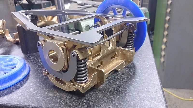 It is upside down so that the axlebox and springs could balance there. The springs were made specially but I am yet to see if they are suitable. They are to scale but may be a bit heavy. Mind you I have pushed the two axleboxes down together and it seems about right. Now to get on to the smaller parts. Also tonight I ordered some scale bolts from the crowd that Roger used a few months ago. Cheers, Mike |
|
|
|
Post by vulcanbomber on Jan 23, 2015 21:15:55 GMT
And looking superb!!!!!! I want, I want, I want!!!!
|
|
44767
Statesman
 
Posts: 538
|
Post by 44767 on Jan 23, 2015 21:27:11 GMT
And looking superb!!!!!! I want, I want, I want!!!! For the 9F it needs to be modified a bit. The rear axlebox guides were a different part having the rear bottom leg extended and bent upwards. This created the angle for the triangular frame which bolted to these legs. You will notice too that the stiffening flanges for the 9F were more like angle iron. The other thing to note is the frame was longer i.e. the pivot point was further back than on the other standards. Other than that the other castings seem to be identical. Maybe you'd like to get some overall dimensions to me for the 9F and I can make parts for the 9F's too. |
|
|
|
Post by vulcanbomber on Jan 23, 2015 21:35:46 GMT
And looking superb!!!!!! I want, I want, I want!!!! For the 9F it needs to be modified a bit. The rear axlebox guides were a different part having the rear bottom leg extended and bent upwards. This created the angle for the triangular frame which bolted to these legs. You will notice too that the stiffening flanges for the 9F were more like angle iron. The other thing to note is the frame was longer i.e. the pivot point was further back than on the other standards. Other than that the other castings seem to be identical. Maybe you'd like to get some overall dimensions to me for the 9F and I can make parts for the 9F's too. Yes sounds like a plan, next time i'm at the museum at York I will have a good study of the pony truck and we can put some sort of plan together to make them up. |
|
44767
Statesman
 
Posts: 538
|
Post by 44767 on Jan 23, 2015 22:17:24 GMT
Here are the critical dimensions for mine. If you just work out what they are on the Warnett drawings I can design the parts to suit. Having said that, you may need to change the stretchers for the pivot and the center to accommodate this height. 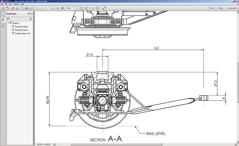 Cheers, Mike |
|
44767
Statesman
 
Posts: 538
|
Post by 44767 on Jan 26, 2015 11:38:16 GMT
Today I machined the axlebox guides. They are a bit tricky as the faces need to be square to each other and the key slot and holes have to be in the correct position relative to the main bearing face. I decided the easiest way was to keep the part held in a small grinding vice and hold that vice in another to present the job on the 3 faces. Here's setting the part in the vice using parallels to get it level and a 2mm drill to space it of the side which gives the correct height each time.  I made this little vice myself as an exercise in toolroom grinding. I made a cylindrical square to use to make sure it was all perfectly square. Now the vice is taken to the milling machine and the bearing face roughed out- 0.3mm machining allowance left on casting 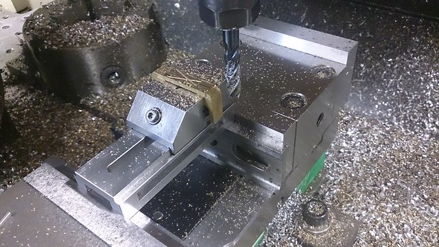 Now transferred to the grinder to finish to size 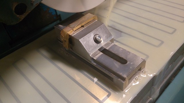 Then back to the mill. With the vice now on its side the datum is calculated off the bearing face 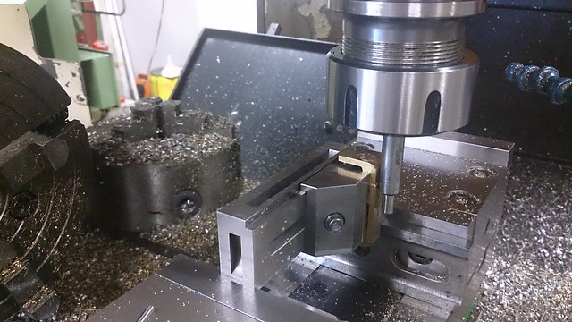 Machining the key slot which is 3.375mm wide (scale 1.5") 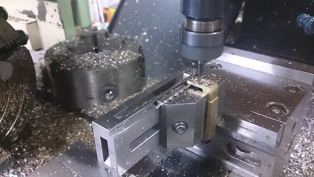 Now the job is turned over, datum reset in X (Y datum remains the same and Z, once set on the second op is constant) 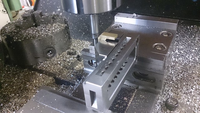 And the second side finished to size with holes. 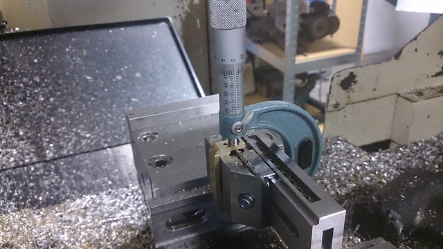 And here it is dry assembled to check. 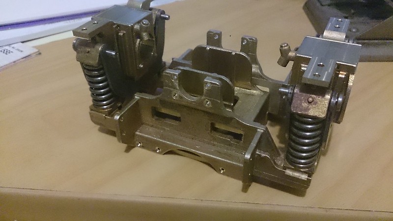 Next will be to finish the triangular frame with some blocks welded on to locate the guides and the blocks to which the guard irons are bolted. Also to do is the pivot. More later, Mike |
|
|
|
Post by Jim on Jan 26, 2015 12:23:12 GMT
I just sit spell bound at the way you have miniaturized the real thing Mike. It's just magic.
Jim
|
|
|
|
Post by Roger on Jan 28, 2015 18:15:51 GMT
Top notch work Mike, very impressive indeed.
|
|
44767
Statesman
 
Posts: 538
|
Post by 44767 on Jan 31, 2015 13:50:45 GMT
So a bit more work on the parts for the pony truck. Most of these parts are simple turning or milling jobs but the beauty of 3D modeling is really showing through. I create the part drawing with the necessary dimensions on it, take it to the work shop and make the part knowing that it will fit just like the assembly drawings shows. 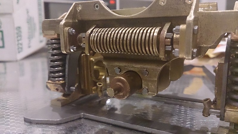 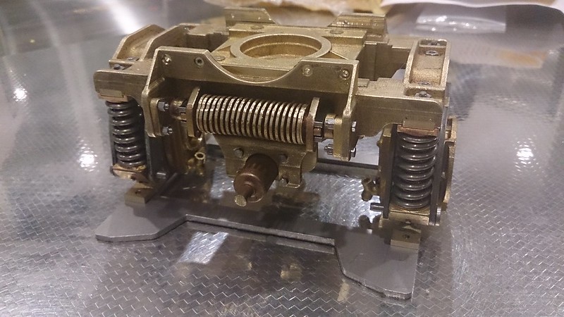 The side control spring is really only a dummy. It was rapid prototyped and cast in silicon bronze. This material is not known for its elasticity! But it does let me see that it will fit next to all the parts around it. The bolts are the ones I found from a supplier in Germany. They are standard metric threads but with scale heads. They are very nicely made and the threads are rolled, not cut. More later, Mike |
|
|
|
Post by Deleted on Jan 31, 2015 13:54:47 GMT
beautiful work Mike.....very impressive...I only wish that I had the time and mentality to take on CAD as it's very clear how much more detail can be incorporated into a design...top stuff sir...
Pete
|
|
|
|
Post by Roger on Jan 31, 2015 13:59:15 GMT
What you're doing is way beyond the realms of conventional 'Model Engineering', it's more like 'True Scaled Engineering'. It's a fascinating twist on what's gone before and I can see this method spawning a lot of super detailed models the like of which have never been seen before. I love it, it's great to be able to bring something new to the table, and that's what I think you're doing.
|
|
44767
Statesman
 
Posts: 538
|
Post by 44767 on Jan 31, 2015 14:03:43 GMT
Yes, I figured it was the natural progression. There's not much further one can go. Even though it is a very detailed model the actual machining is very easy.
|
|
|
|
Post by fostergp6nhp on Jan 31, 2015 16:44:11 GMT
The square/rectangular section side control springs, could these be cast in something springy so you get the correct appearance and they work. Also are the erode faced side control dampers going to be working or dummy?
|
|
|
|
Post by Deleted on Jan 31, 2015 17:17:40 GMT
Beautifully done I must say.
John
|
|
44767
Statesman
 
Posts: 538
|
Post by 44767 on Jan 31, 2015 23:01:07 GMT
The square/rectangular section side control springs, could these be cast in something springy so you get the correct appearance and they work. Also are the erode faced side control dampers going to be working or dummy? Yes, I'm thinking they could be cast in a spring steel so I'll look into that. The dampers will have a sprung plunger so it will work but probably isn't necessary in this scale. |
|
44767
Statesman
 
Posts: 538
|
Post by 44767 on Feb 1, 2015 13:29:54 GMT
Today I machined the center pivot slide's top face and made the keeps to hold it in place. The screws holding them on are M1.4's. That's about the size of 12BA. The larger ones are temporary 7BA ones which will be replaced with M2.5 bolts  Also I machined the damper cylinders and plungers. 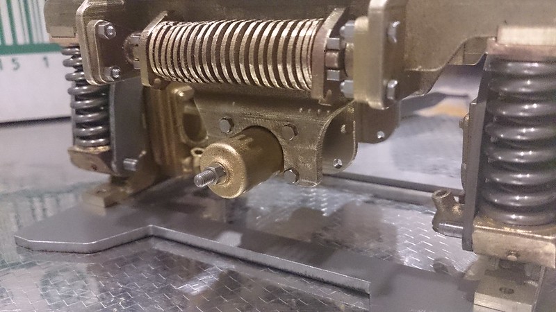 Tomorrow I hope to get the axles done and maybe a pair of wheels. |
|
|
|
Post by Oily Rag on Feb 3, 2015 3:58:23 GMT
So a bit more work on the parts for the pony truck. Most of these parts are simple turning or milling jobs but the beauty of 3D modeling is really showing through. I create the part drawing with the necessary dimensions on it, take it to the work shop and make the part knowing that it will fit just like the assembly drawings shows. Inspirational work, I am enjoying this thread immensely I sat down with the text books and persevered with learning 3D Solid Works. I agree that one can ensure it all goes together correctly as it is proven in the assembly. I have been working away on a Queensland Railways C17 #253 as delivered in 1920 using 3D and there is no way this 52 yo is going back to a drafting board. I am 110% converted. Just setting up the new workshop and need to finish my current loco before I start the good one. I have many questions in regards to 3D printing and your casting processes, but maybe later. Please keep posting regularly your process, please! |
|
44767
Statesman
 
Posts: 538
|
Post by 44767 on Feb 7, 2015 6:50:51 GMT
After another couple of [late] nights the truck is nearly finished.  It's more difficult than I thought to assemble but it can be done. All holes were done to the drawings and all was correct. The exception was the two holes each side where the stays bolt onto the triangular frame. I put these in the stays but used this, once assembled, to spot through into the frame. Since this photo I have drilled some 1mm holes in the frame to locate the blocks and brackets which register the bottom of the axlebox guides, life guards mounting blocks and the lubrication point brackets. Mike |
|
|
|
Post by Roger on Feb 7, 2015 7:54:30 GMT
What a fabulous piece of work, I love it. Personally, I think if you've got a mill, I would avoid any spotting through, it's another source of errors. I think you're far better off putting all the holes in using the mill if you can.
|
|