44767
Statesman
 
Posts: 538
|
Post by 44767 on Feb 7, 2015 8:02:31 GMT
What a fabulous piece of work, I love it. Personally, I think if you've got a mill, I would avoid any spotting through, it's another source of errors. I think you're far better off putting all the holes in using the mill if you can. Normally I would Roger, but these were the four holes that were on the frame where it is bent upwards. I didn't do my drawing of this part so that the holes were parametric. Well they are there in the model but I wanted to drill all these before the frame was bent and couldn't guarantee they'd be in the correct place after bending. It is one of the things one has to think about when you plan how to model a part in 3D. Mike |
|
|
|
Post by Roger on Feb 7, 2015 8:17:21 GMT
Ah, I see, I thought there would be a good reason. I still 'spot through' on an assembly in 3D CAD sometimes though. It's sometimes easier to assemble parts in a model and then project the holes from another part onto the one I'm adding.
|
|
44767
Statesman
 
Posts: 538
|
Post by 44767 on Feb 7, 2015 8:43:22 GMT
Ah, I see, I thought there would be a good reason. I still 'spot through' on an assembly in 3D CAD sometimes though. It's sometimes easier to assemble parts in a model and then project the holes from another part onto the one I'm adding. If you do this Roger, it's best practice to go back into the part, delete the reference to the other part and dimension the part itself (now that you know where the hole has to be). The sketch should stay where it was. Otherwise you need that second part in that assembly along with the part you're opening to know where the hole is. Mike |
|
|
|
Post by Roger on Feb 7, 2015 9:04:45 GMT
That doesn't seem to be a problem in Ablibre, perhaps it's that way I do it. I edit the part that's having holes added to it while I can see the whole assembly ghosted in. When it gets saved and the whole assembly saved, those features are permanently present in the individual part models.
|
|
|
|
Post by Rex Hanman on Feb 7, 2015 9:22:05 GMT
I was chuffed with my pony truck......then I saw yours.  Brilliant! |
|
44767
Statesman
 
Posts: 538
|
Post by 44767 on Feb 7, 2015 9:24:42 GMT
But if you were to give the part file to someone else the dimensions to the hole would fall over. Yours works alright because the programme knows where to look for that information i.e. your part is referencing another.
|
|
|
|
Post by Roger on Feb 7, 2015 10:04:49 GMT
But if you were to give the part file to someone else the dimensions to the hole would fall over. Yours works alright because the programme knows where to look for that information i.e. your part is referencing another. I don't think that's true. The information for each part is contained within the model for that part which is outside of the assembly. I can open those parts in isolation from the assembly and the holes are there in the model. When I modify the parts this way, I use Project to Sketch but I don't maintain any association with the holes underneath. It's just a way to pasting the hole pattern onto a sketch in the part I'm editing. I don't know if it will even let me maintain association with the original sketch, it sounds dangerous and unlikely to me for the sorts of reasons you mention. There are no references from one part to another when it comes to sketches. |
|
44767
Statesman
 
Posts: 538
|
Post by 44767 on Feb 7, 2015 10:38:59 GMT
The Alibre must automatically "fix" (that is constrain) the sketch. SW shows in the feature tree that a sketch has outside references. Sometimes you want them there. e.g. I leave the references there while I'm drawing up the frames so that if I change a stretcher the holes in the frame moves with it. Once everything is finalised I go through and constrain the sketches with actual dimensions and remove the reference.
|
|
|
|
Post by Roger on Feb 7, 2015 11:05:48 GMT
I don't think that's necessary, because the sketch isn't reference to the original part. There's nothing broken to fix. It's no different to a copy and paste.
I think we must be talking about different things. Using Project to sketch to copy lines from another part in an assembly is no different to doing that in a stand alone part. The default is to just copy the lines to the new sketch, there's no association to the original sketch, they are just lines.
If you then go on to constrain those items then it may be different but I've never had any issues with what I've described. If you change something in a part that's constrained, it just shows that the constraint in the assembly is broken. That can and does happen if I make radical changes to a part when editing from inside the assembly but it's easily fixed by pointing the broken constraints to the new feature I want it to refer to.
|
|
|
|
Post by Deleted on Feb 7, 2015 11:16:13 GMT
Using Project to sketch to copy lines from another part in an assembly is no different to doing that in a stand alone part. The default is to just copy the lines to the new sketch, there's no association to the original sketch, they are just lines. I didn't realise you could do that Roger. I'll have to look into it as it would be useful at times. John |
|
44767
Statesman
 
Posts: 538
|
Post by 44767 on Feb 7, 2015 11:39:45 GMT
In SW the term is "fix" (as in "hold fast"); thinking back I think the term in Alibre is "lock" So these sketches that you project from another part in an assembly to a sketch, without reference must be free to move if you pull on one of the endpoints, for example, in the sketch you're creating? Sure they'll stay where they are if you are careful but as I said earlier, the best practice is to fully define (Allibre- read fully constrain) the sketch.
|
|
|
|
Post by Roger on Feb 7, 2015 13:04:54 GMT
In SW the term is "fix" (as in "hold fast"); thinking back I think the term in Alibre is "lock" So these sketches that you project from another part in an assembly to a sketch, without reference must be free to move if you pull on one of the endpoints, for example, in the sketch you're creating? Sure they'll stay where they are if you are careful but as I said earlier, the best practice is to fully define (Allibre- read fully constrain) the sketch. I'm not sure that best practice is to constrain everything. Things stay where they are unless you cause them to move so it's not necessary to constrain every line. If you use a Linear sketch pattern, it doesn't automatically create constraints for those and I certainly wouldn't go back and dimension them or constrain them. When you come to use Sketch Move, it's a pain if everything is constrained because it won't let you move things until you've removed them. I think you're far better off constraining where it's helpful and leaving it off where it isn't. I'm likely to use an = constraint on a group of holes where I think the sizes might change and I'm a big fan of them. I just think it's counter productive to get carried away and try to constrain everything too far. For example, if a circle is constrained to be a tangent to a line, is there any benefit in then fixing the centre or the circle? Personally, I think that get in the way of the flexibility of creating something with constraints that help you control geometry while remaining flexible in the dimensions you want to change. In that example, you could drag the centre of the circle, but why would anyone do that? |
|
44767
Statesman
 
Posts: 538
|
Post by 44767 on Feb 7, 2015 20:26:10 GMT
You miss the point, Roger. Best practice is to have sketches and assemblies full defined. I know because I spent two years in the design office detailing and checking drawings and designs and one of the items on the list to check is exactly that. By all means use the constraints to make the sketch with the design intent so that if a dimension is changed the sketch updates as you require This is the whole point of parametric modelling but by the time the sketch is finished it should be defined fully.
Now, enough on this matter; there are other threads to discuss this sort of thing, This one is for my class 3 build.
|
|
|
|
Post by joanlluch on Feb 9, 2015 8:24:50 GMT
I take a different approach for parts and assemblies.
For parts, what I do is to constrain everything to have the minimal degrees of freedom that define the essential features I need at a time, usually only one or two. When I consider the part finished I may fully constraint any remaining freedom.
For assemblies, I never over-constraint. Constraints are limited to just one above what would make the model unstable. By doing this I prevent a lot of chained constraint errors that would occur in an over-constrained model when I replace a part or change its dimensions.
I do not know whether this is an usual approach but it's something that works for me.
|
|
44767
Statesman
 
Posts: 538
|
Post by 44767 on Jul 14, 2015 9:24:25 GMT
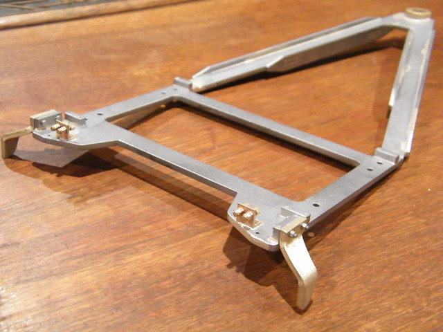
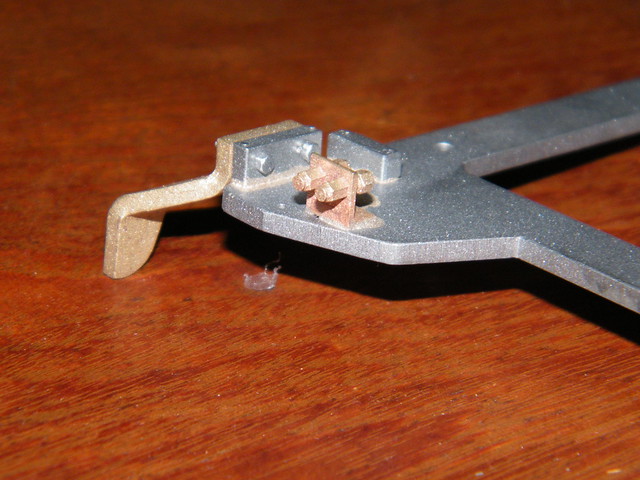
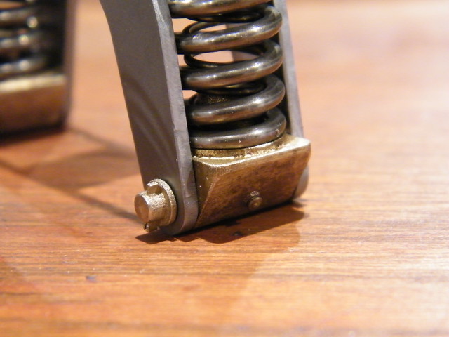
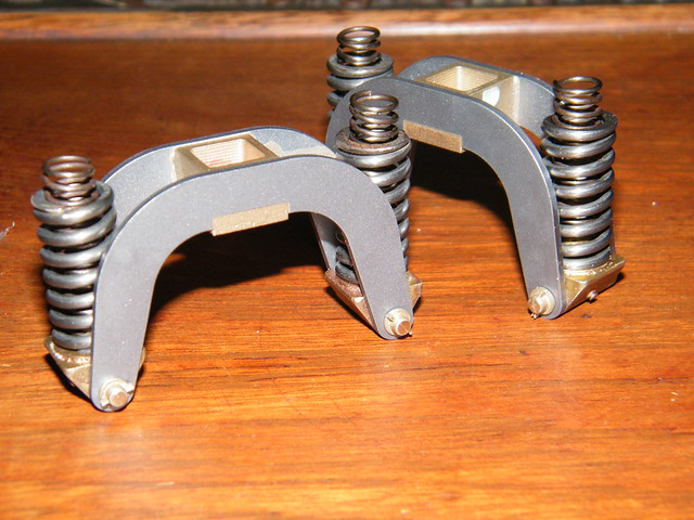
Hello again everyone! I must apologise for not frequenting the forum much recently. I have had trips to China and last time it was difficult to get on even this website. My return home saw me trying to sort out the printer which seems to be working much better now. The issue I had with it was quite a furry finish down the sides of the part and the sides of any feature on it. It caused the finished wax to lack some detail and I was not confident to do some jobs because of it. The fault turned out to be the pump which pumps the hot, liquid wax up to the print head had a small leak in the seal. This was allowing air into the wax which got whipped up to a foam. This then must have come out of the print head like snow- spraying in all directions. Once the service engineer considered this as the fault he changed the pump for one in the showroom and without any other alteration the machine prints perfectly again. Anyway I have done a bit of work on the pony trucks. Here is the bridle frame soldered together and with the guard irons (some may say life irons) along with lost wax castings of the greasing points for the axlebox guides  Here's a close up of the detail  This image shows my sneeky way of doing the pins for the spring beams   You can see that the pin itself is a simple turning job but the end only protrudes just past the beam. It has a tapped hole in its end and the little lost wax casting representing the washer, the end of the pin and the split cotter screws onto it by means of a 2mm piece of threaded rod. As in full size there are two coil springs. The weight of the loco will compress the light inner spring until it rests on the larger spring. The light springing will let the wheel dip into hollows in the track. The heavier spring will also allow the wheels to move upwards but with more resistance. This should stop the truck riding up and derailing on trailing ground level points. Well, I hope to be able to give far more regular updates from now on. Mike |
|
|
|
Post by ejparrott on Jul 14, 2015 10:24:37 GMT
Nice work Mike, are you using left hand and right hand wound springs for those? Doug mentions the same in his CL4 stuff, but I haven't to date noticed an option to buy them - not that I've paid much attention as I'm not working on that engine yet
|
|
44767
Statesman
 
Posts: 538
|
Post by 44767 on Jul 14, 2015 10:31:04 GMT
Yes they are wound opposite hand to each other. This stops the coils binding together. Someone is going to look at mine and compare to full size and say that my outer springs are wound the wrong hand so here I am getting in first!
I had a hundred of each wound by a spring maker. Once the run is long enough they are not very expensive. e.g. if you get one made it would be about $150.00 but to get 100 wound it was $200.00
|
|
44767
Statesman
 
Posts: 538
|
Post by 44767 on Mar 12, 2017 3:07:31 GMT
|
|
Greg
Involved Member
  
Posts: 84
|
Post by Greg on Mar 12, 2017 6:54:40 GMT
Very nice  |
|
sis
Seasoned Member

Posts: 113
|
Post by sis on Mar 12, 2017 11:51:07 GMT
Mike,
Very impressive cylinders and thank you for sharing. It looks more and more like this thread is providing us with a view of the hobby's future today. I am sure 3d wax printing method is going to be the future of the pattern making for fine detail castings. With this approach how you did you get the ceramic out of the passage ways? Or did you re-design the internals to be more appropriate for the lost wax casting method.
By the way I sent you a message.
Thanks,
Steve
|
|