|
|
Post by 92220 on Mar 12, 2017 18:43:10 GMT
Hi Mike.
VERY impressive castings!! They are very similar to the 9F cylinders with one big exception - What is the second big flange on the top of the valve chest? The back one is the steam inlet but what is the front one? Pity this process wasn't around when I fabricated my cylinders!!
|
|
|
|
Post by Deleted on Mar 12, 2017 21:08:41 GMT
love the cylinder Mike..... brilliant..
Pete
|
|
44767
Statesman
 
Posts: 538
|
Post by 44767 on Mar 13, 2017 3:22:37 GMT
Hi Mike. VERY impressive castings!! They are very similar to the 9F cylinders with one big exception - What is the second big flange on the top of the valve chest? The back one is the steam inlet but what is the front one? Pity this process wasn't around when I fabricated my cylinders!! The other port was blanked off in full size. This cylinder came directly from the LMS and is used on the class 3 tank and class 3 mogul as well as the class 4 mogul. I am guessing that it was for a snifter valve. |
|
44767
Statesman
 
Posts: 538
|
Post by 44767 on Mar 13, 2017 7:30:36 GMT
Mike, With this approach how you did you get the ceramic out of the passage ways? Or did you re-design the internals to be more appropriate for the lost wax casting method. Thanks, Steve The foundry, at first, wouldn't do the job. They didn't think the casting would come out of the ceramic in one piece. I asked for them to do it anyway as it was a trial to see if the method was viable. I had already had one done in silicon bronze which will have cast iron liners in it but I wanted to see if it would work in cast iron to avoid the liners being separate (except the valve chest liners as they need to be separate by design). I changed nothing on the drawing to make anything easier so, yes, there was difficulty getting the ceramic out of the valve chest especially. The mould is very fragile in tension but strong in compression so getting internal material out doesn't work just by hitting it! The ceramic does however soften in caustic soda so it was boiled in a pot of this for a while and then the loosened mould material was removed easily with bead blasting. |
|
|
|
Post by 92220 on Mar 13, 2017 8:39:14 GMT
Thanks Mike. I did wonder if it was for a snifter valve but thought it was a bit big. Anyway, superb castings! Oh how I wish you had been around when I made my pony truck!! Had to machine everything from solid steel!! 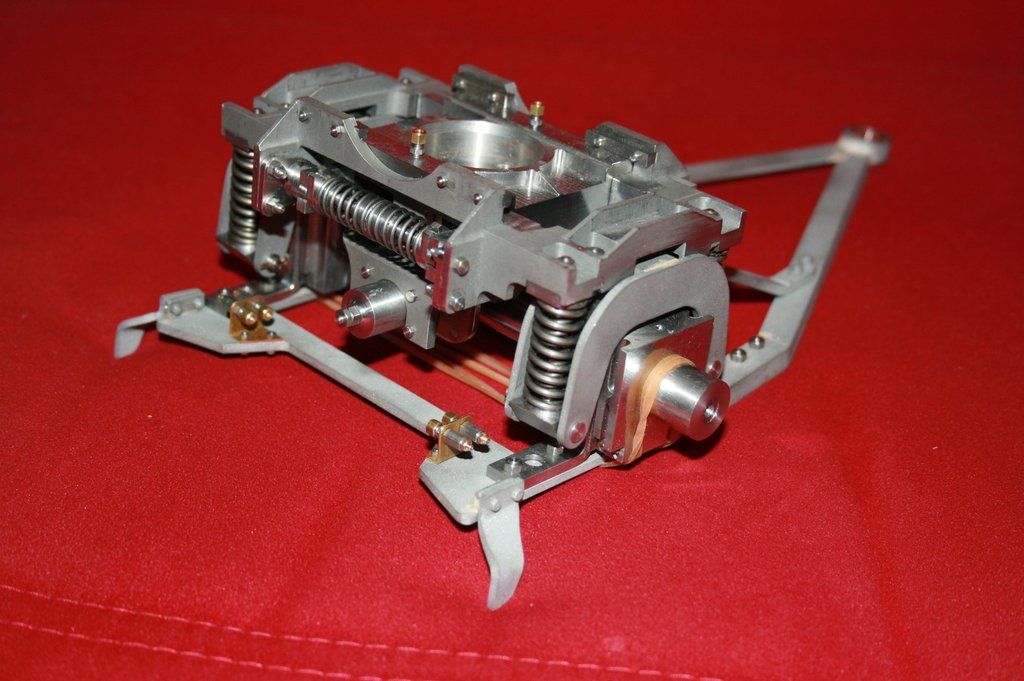 |
|
sis
Seasoned Member

Posts: 113
|
Post by sis on Mar 13, 2017 18:51:33 GMT
Mike,
Thank you very much for explaining how you managed to design and produce cylinders with passage ways such as you have. I have to say the more I look at these cylinders and refer to drawings for similar designs the more impressed I am. A job well done.
Steve
|
|
44767
Statesman
 
Posts: 538
|
Post by 44767 on Mar 14, 2017 3:47:54 GMT
Oh how I wish you had been around when I made my pony truck!! Had to machine everything from solid steel!! Great looking pony truck, Bob. A fantastic bit of machining. |
|
44767
Statesman
 
Posts: 538
|
Post by 44767 on Mar 16, 2017 6:24:45 GMT
Today I picked up some lost wax castings for the class 3 which are done in steel. Without a doubt they have turned out beyond what I was expecting. This will open up huge possibilities for castings where silicon bronze is not the first choice material. They are very clean and have taken the same sort of detail seen in the bronze castings. Wall thickness cannot be as thin but as long as the area is not large, this can be down to about 1mm. 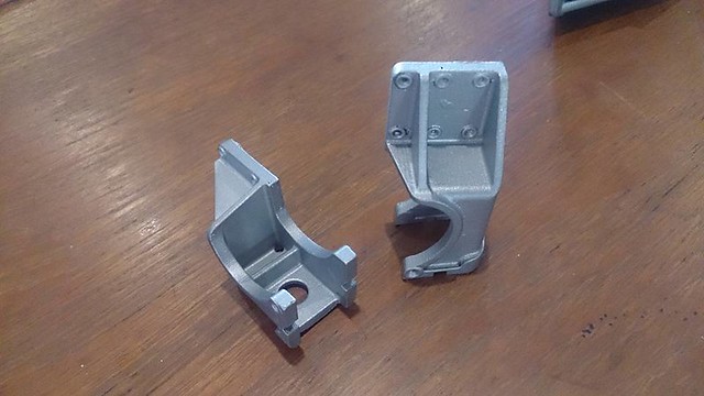 A pair of spring hangers for the driving wheel suspension 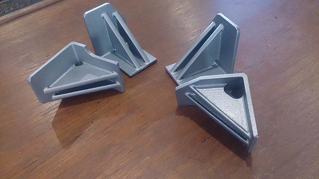 The four buffer beam brackets 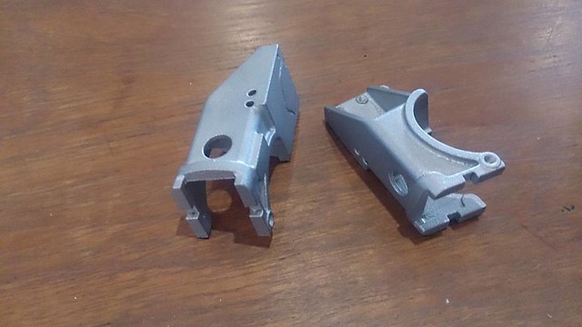 The spring hangers. Note the holes in the corners; these are on the drawing and are there so that the cross section remains constant (there would otherwise be a heavy section here) and so the cooling metal does not shrink in the corner causing cracks and pulling the casting out of shape. The process for the steel casting is different to that used for the lower melting point alloys. It is much more labour intensive and also takes longer. A lead time of three weeks is typical as opposed to next day with the bronze castings. Therefore the castings are more expensive but depending on the size, they are still a very good option. This steel is 4130 which is a medium high tensile steel. It requires heat treatment to make it machinable but this is included in the cost of the castings for these small parts. So I am a very happy chappy! |
|
|
|
Post by 92220 on Mar 16, 2017 9:14:59 GMT
They are fantastic Mike!! This opens up a whole new set of options for model engineers!!
Bob
|
|
|
|
Post by Jim on Mar 16, 2017 12:29:25 GMT
I couldn't agree more Bob, Mike's work is just superb and with Pete and Adam sets a whole new standard for the hobby.
Jim.
|
|
|
|
Post by steamer5 on Mar 17, 2017 0:29:40 GMT
Hi Mike,
Just read thru this thread! That is impressive work you are doing there. Definitely going to keep on eye on what you are up to. That cylinder is a work of art in its own right. Can I ask please what are the bore sizes & the weight?
cheers Kerrin
|
|
44767
Statesman
 
Posts: 538
|
Post by 44767 on Mar 17, 2017 6:57:21 GMT
Hi Mike, Just read thru this thread! That is impressive work you are doing there. Definitely going to keep on eye on what you are up to. That cylinder is a work of art in its own right. Can I ask please what are the bore sizes & the weight? cheers Kerrin The casting as it is weighs 899 grams. Its bore, unmachined, is 39mm and the valve chest bore is 24mm. |
|
|
|
Post by steamer5 on Mar 17, 2017 7:21:50 GMT
Hi Mike,
Thanks for that. That's a lot less than a standard casting I guess, & way less machining to do as well.
Cheers Kerrin
|
|
sis
Seasoned Member

Posts: 113
|
Post by sis on Mar 17, 2017 9:40:52 GMT
Mike,
I've sent you another PM. I think these posts have swung it and instead of fabrication I need to raid the piggy bank and get 2 cylinders form Mike! Keep up the outstanding work and please do post!
Steve
|
|
44767
Statesman
 
Posts: 538
|
Post by 44767 on Jul 7, 2017 7:17:29 GMT
|
|
44767
Statesman
 
Posts: 538
|
Post by 44767 on Jul 7, 2017 7:33:58 GMT
Here are two which have been soldered together. 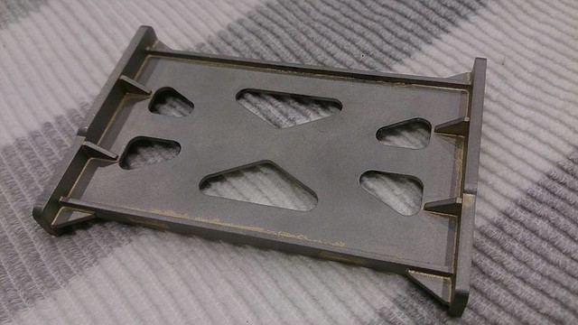 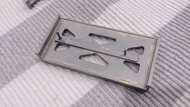 |
|
|
|
Post by 92220 on Jul 7, 2017 8:11:12 GMT
Lovely job Mike. Now for the silversoldering! Must admit, when I did mine I didn't worry too much about keeping small, neat, solder joints. When the fabrication was cool I just fettled them with a dentist drill (When I started the loco I had a very interested dentist!). It worked out well because the fabs looked like castings once painted.
Another trick I used was to use oxy for the silversoldering, so that the flame was concentrated on the joint, and have the stretcher clamped to a thick piece of steel. That way only the stretcher got really hot, and the steel plate (1/2" thick) kept the stretcher flat until it was cool and distortion was minimal.
Bob.
|
|
44767
Statesman
 
Posts: 538
|
Post by 44767 on Jun 23, 2018 5:08:12 GMT
Well overdue now but I will start recording here again where the class 3 project is up to. There's lots of water under the bridge since the last post! Notably, there are now three chaps building their own models in parallel with me. One, in particular, keeps me on my feet trying to supply parts and drawings to him as he needs them. Here are a few of the stretchers he has fabricated from my laser cut kits then machined. 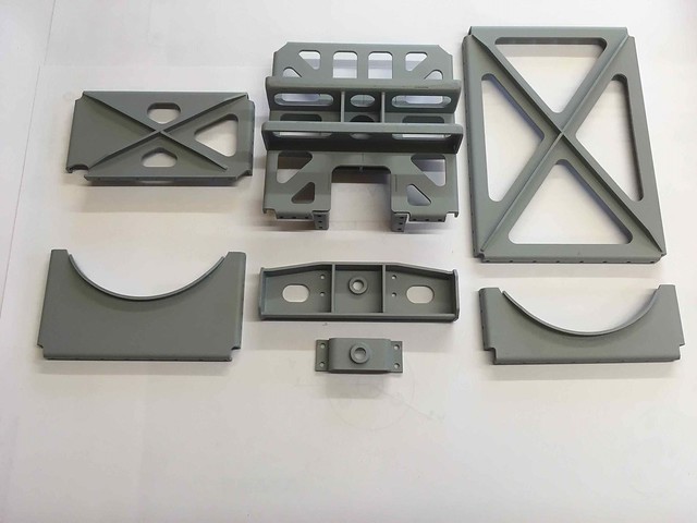 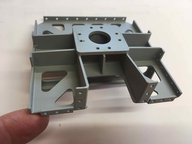 I'm hoping to have a set of driving wheels cast in time for me to take to the UK in August. Generally, though, progress has seen all of the stretchers up to fabrication stage with all drawings for them done. The frame plates have had a small batch made but the drawings need finalising. A trial main axlebox and its keep have been cast to make sure they work in cast iron. On the design side, I have virtually finished the cab floor. 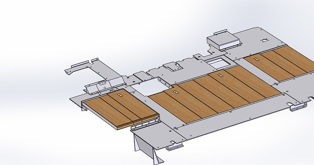 This needed to be done to check all the brackets around this area were correct. It will be one drop in sub-assembly. We took the decision to reduce the distance between the frame plates by 5mm (2.5mm per side) to allow the suspension to work fully on less than scale radii track. This took quite a bit of rework to the design as every stretcher had to be altered and every bracket outside the frames had to be increased in length by 2.5mm (including the cylinders and motion brackets.) Here's the sort of thing I have to make sure still fits 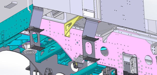 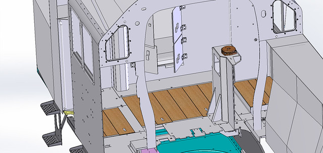 I also am modifying the model where the reverser mounts. In full size this mounted on a plinth which was part of the LH tank fabrication. It would mean disconnecting the reverser before the tank could be removed- a task not possible with over scale hands! The reverser now sits on a bracket attached directly to the frame and so the tank is free to be removed at will. Right, that shold be enough to go with for a bit! |
|
44767
Statesman
 
Posts: 538
|
Post by 44767 on Jun 25, 2018 3:28:38 GMT
I have been machining the die for the driving wheels over the last week. I took it to the foundry this afternoon so they could trial it. The die was put straight into the moulder and a few seconds later this popped out. I am very pleased with it. I had measured the pony truck wheel compared to the cavity in the die to find the overall shrinkage rate. This turned out to be 2.0%. Knowing that cast iron shrinks 1% from the size of the wax, this wax was measured and it is 0.05mm from the calculated size. Yeah! 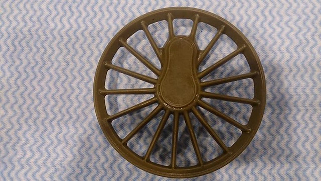 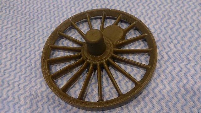 |
|
|
|
Post by 92220 on Jun 25, 2018 17:27:11 GMT
Hi Mike.
They are looking really good! Are they waxes or final CI castings? If they are the finished CI casting, fine, there is obviously no problem with pouring. If they are the waxes, perhaps some detail on the problems of producing my castings might help.
When they first tried, they poured into the centre of the wheel and expected the molten metal to travel up the spokes to fill the rim. My rim was, admittedly, bigger than yours because it was of a size that allowed a standard flanged wheel to be made out of the casting. Anyway, the casters found that the metal cooled unevenly while being pushed through the spokes, possibly due to the crank boss, and they couldn't get perfect castings. They then added 4 more runners equispaced around the rim, on the rear face of the wheel. That did solve the problem, by allowing the molten metal to fill the spokes from each end, quickly. Just having the 5 runners instead of 1 central runner, got rid of all blowholes too.
Bob.
Edit:- Mike. I forgot to say why I chose 316J stainless over CI. It was because my spokes were scale section, as I think yours are. With CI there was a very real risk of the spokes cracking when the castings cooled due to the uneven shrinkage while cooling. I had the thickness of the central boss and the thickness of the rim with the thin spokes between. You might be OK with your thinner rim where you don't cater for a fully machined wheel like I did, but it might be something to bear in mind if you do get spoke cracking. Stainless can stand quite considerable stretching and contracting before it cracks, where cast iron can't. That is why commercial CI wheel castings have quite overscale spokes. It dramatically cuts the risk of cracking due to stresses built up in the castings during cooling. Machining can increase stresses and then cause those stresses to initiate cracking during the machining. Just so you know there is a solution if the worst does happen. Hopefully your thinner rims will get over the problem. |
|