|
|
Post by Roger on Apr 17, 2015 20:55:36 GMT
Hi Tim, Superb work as always. I have a question for you about the wire eroding. How do you set up the job relative to the wire centre line? Go back a bit and you'll see a small drilled hole in the buckles Roger, you shove the wire through the hole then touch the hole with the wire(moving the machine table) to find the edges of the hole. At least that's how the one we have at work is done. Thanks Dave, but how do you know it's touched? It's an accurate piece of kit so I assume there must be a way to determine that to a high degree of precision? |
|
|
|
Post by vulcanbomber on Apr 17, 2015 21:10:09 GMT
Go back a bit and you'll see a small drilled hole in the buckles Roger, you shove the wire through the hole then touch the hole with the wire(moving the machine table) to find the edges of the hole. At least that's how the one we have at work is done. Thanks Dave, but how do you know it's touched? It's an accurate piece of kit so I assume there must be a way to determine that to a high degree of precision? Not on ours but it's like every other machine at work in that it's old and crippled..... If you were using our wire you'd wire the hole and then the profile in 1 setup and from solid. It runs electric through the wire so when contact is made current flows... When it's cutting it's the water that carries the arc to cut, if the wire touches, it breaks and Steve (it's main operator but Ed does a bit) starts pulling his hair out. |
|
tim
E-xcellent poster
  
Posts: 236
|
Post by tim on Apr 17, 2015 21:44:56 GMT
Go back a bit and you'll see a small drilled hole in the buckles Roger, you shove the wire through the hole then touch the hole with the wire(moving the machine table) to find the edges of the hole. At least that's how the one we have at work is done. Thanks Dave, but how do you know it's touched? It's an accurate piece of kit so I assume there must be a way to determine that to a high degree of precision? On ours, once set, it threads its wire through the hole using a jet of water then edge finds off 4 points in the hole and sets the datum. |
|
|
|
Post by Roger on Apr 17, 2015 21:52:05 GMT
Thanks Dave, but how do you know it's touched? It's an accurate piece of kit so I assume there must be a way to determine that to a high degree of precision? On ours, once set, it threads its wire through the hole using a jet of water then edge finds off 4 points in the hole and sets the datum. Thanks Tim, that sounds like a very clever piece of kit, and very useful. What was the cycle time for your cutouts? |
|
tim
E-xcellent poster
  
Posts: 236
|
Post by tim on Apr 17, 2015 22:06:27 GMT
On ours, once set, it threads its wire through the hole using a jet of water then edge finds off 4 points in the hole and sets the datum. Thanks Tim, that sounds like a very clever piece of kit, and very useful. What was the cycle time for your cutouts? They took about 25 mins each. And about 2 weeks to get a chance to use the machine since they are constantly on the go. |
|
|
|
Post by Roger on Apr 17, 2015 22:12:47 GMT
Thanks Tim, that sounds like a very clever piece of kit, and very useful. What was the cycle time for your cutouts? They took about 25 mins each. And about 2 weeks to get a chance to use the machine since they are constantly on the go. That's surprisingly quick when you think of how it's removing the metal. It's a great answer to getting almost square corners. I suppose you could wire erode some HSS crosshead slides using that, they would last forever! |
|
tim
E-xcellent poster
  
Posts: 236
|
Post by tim on Apr 18, 2015 9:58:53 GMT
hi tim, spring buckles are one of the things i hate making and your's are quite superb. i dont suppose you would consider commisions? i dont know how far dave (Midland) has got with his Aspinall buckles but i havent started mine for Stepney! cheers, julian Sorry for the late response Julian I somehow missed your post last night, thanks for your comments. I've never really thought about it before but I guess I would consider the odd commission, If it helped someone out. Tim. |
|
|
|
Post by silverfox on Apr 18, 2015 23:13:21 GMT
Tim
If you ever go in that direction could i get in the queue for half a dozen loco plus half a dozen tender spring buckles please?
Ron
|
|
tim
E-xcellent poster
  
Posts: 236
|
Post by tim on May 3, 2015 19:38:37 GMT
Hi all, made a start on the brake shaft this weekend. I`m showing the drawing, as it suggests making this as a fabrication, however I`ve decided to go about it a slightly different way. So, the drawing... 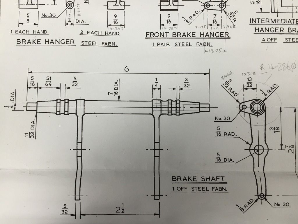 And the plan,... 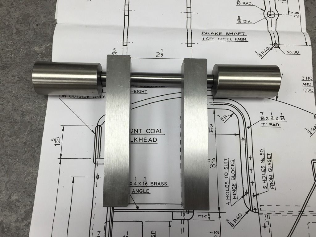 First up the shaft, this has 2 small keyways at each end which will allow the main arms to align correctly. 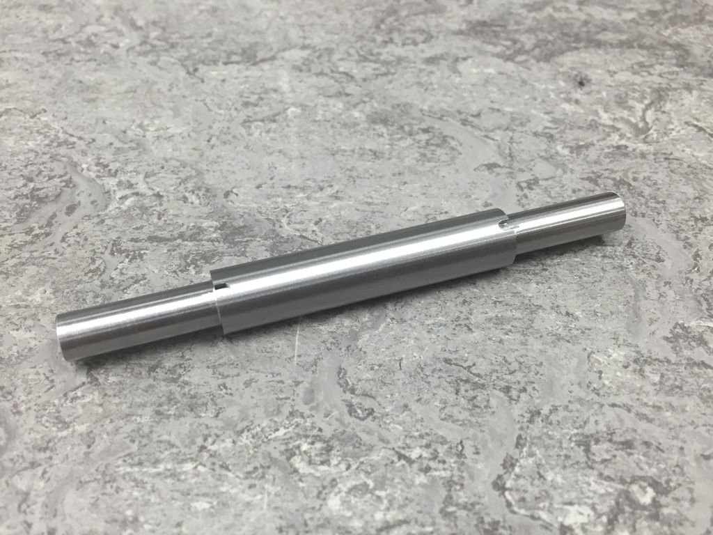 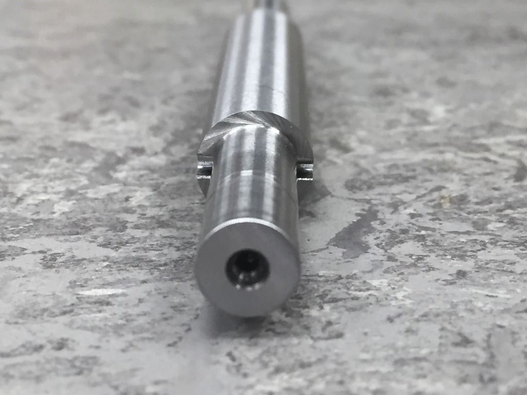 Next the main arms, these I`ve made in a similar way to the brake hangers, with 20mm extra material on each end, making them easier to hold during manufacture. The first job being to rough out either side to allow them to spring. As can be seen I`ve currently only finished one side at the moment but this allowed a trial fit to the shaft. 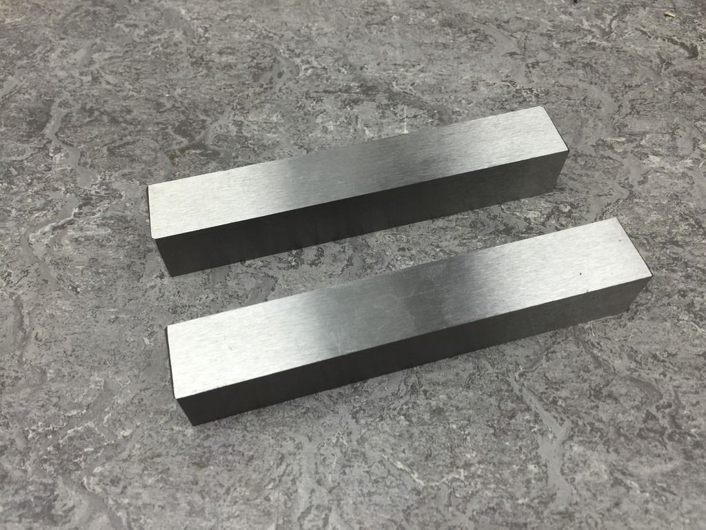 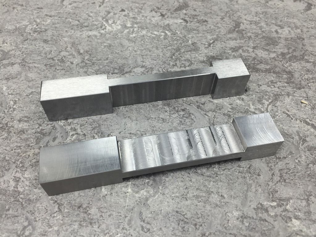 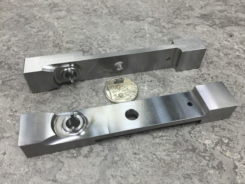 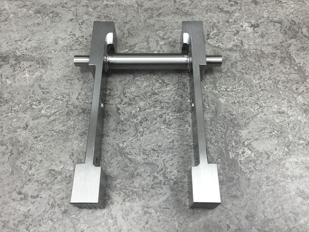 More soon. Tim. |
|
tim
E-xcellent poster
  
Posts: 236
|
Post by tim on May 15, 2015 9:14:27 GMT
So a bit more progress on the brake shaft, to complete the main arms I needed to make a fixture to bolt them to, thus allowing the profile to be machined. 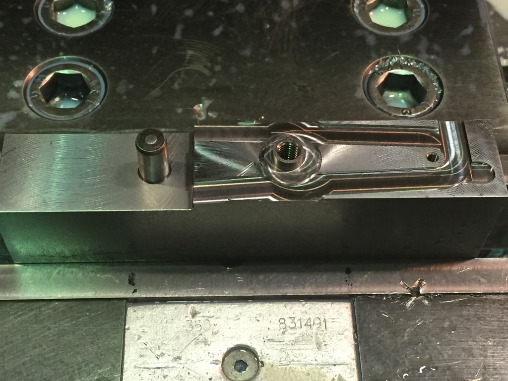 i34.photobucket.com/albums/d146/heilan_lassie/56F8126D-7862-4E95-AC8B-9742E0B83BEE_zpscixdcxl9.jpg i34.photobucket.com/albums/d146/heilan_lassie/56F8126D-7862-4E95-AC8B-9742E0B83BEE_zpscixdcxl9.jpg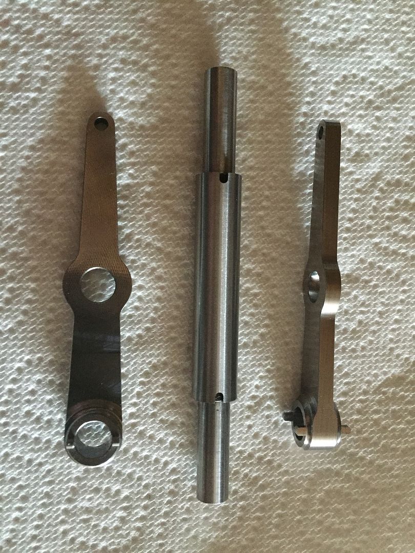 Next I made a start on the outside sections, turning to start with, 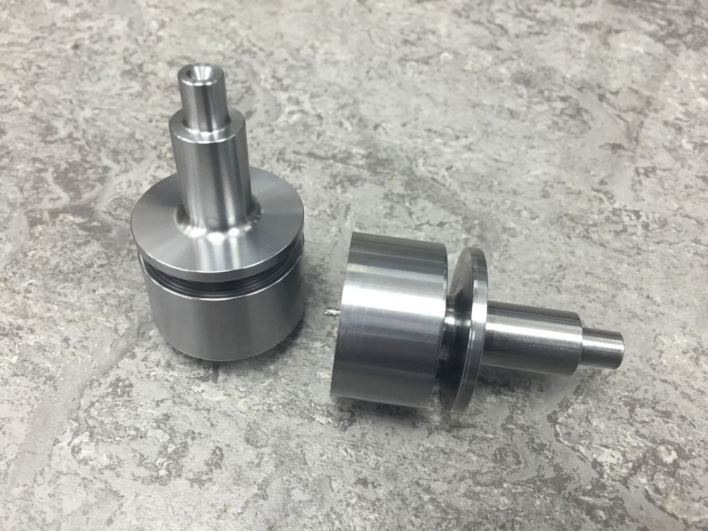 and then milled on the reverse side to put the tiny keyways in for the necessary alignment and the no.30 hole. 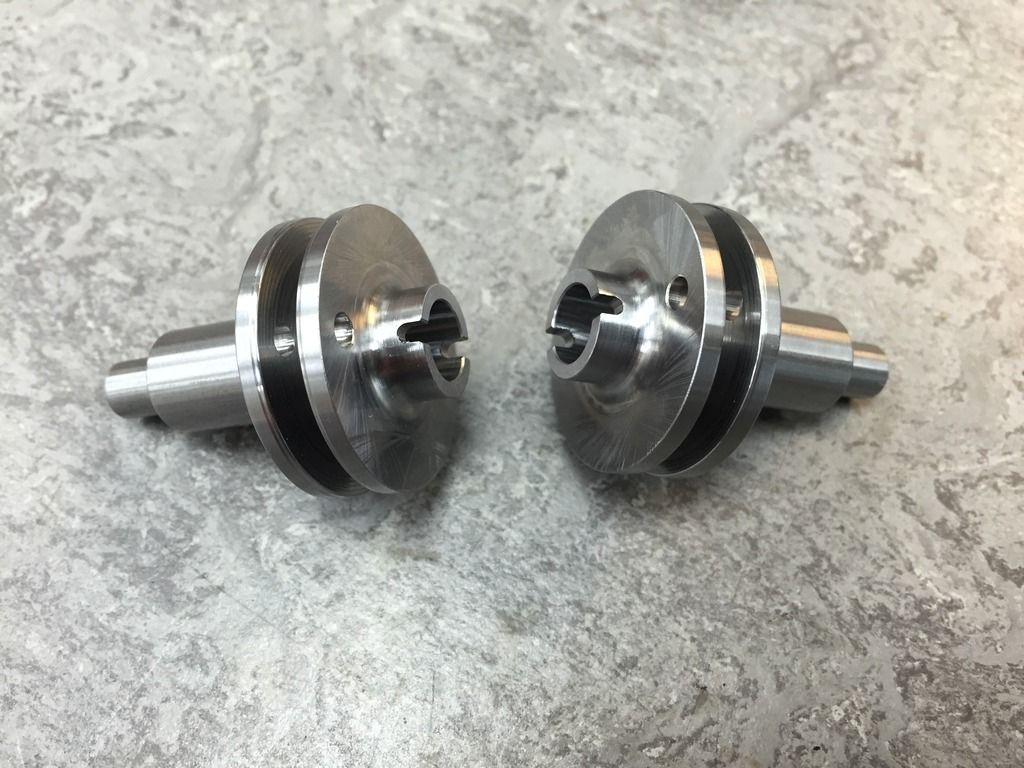 These are not quite finished as there is a small profile around the grooved part to do yet, but just a trial fit to see all is well, then they can be loctited together forever. Regards Tim. 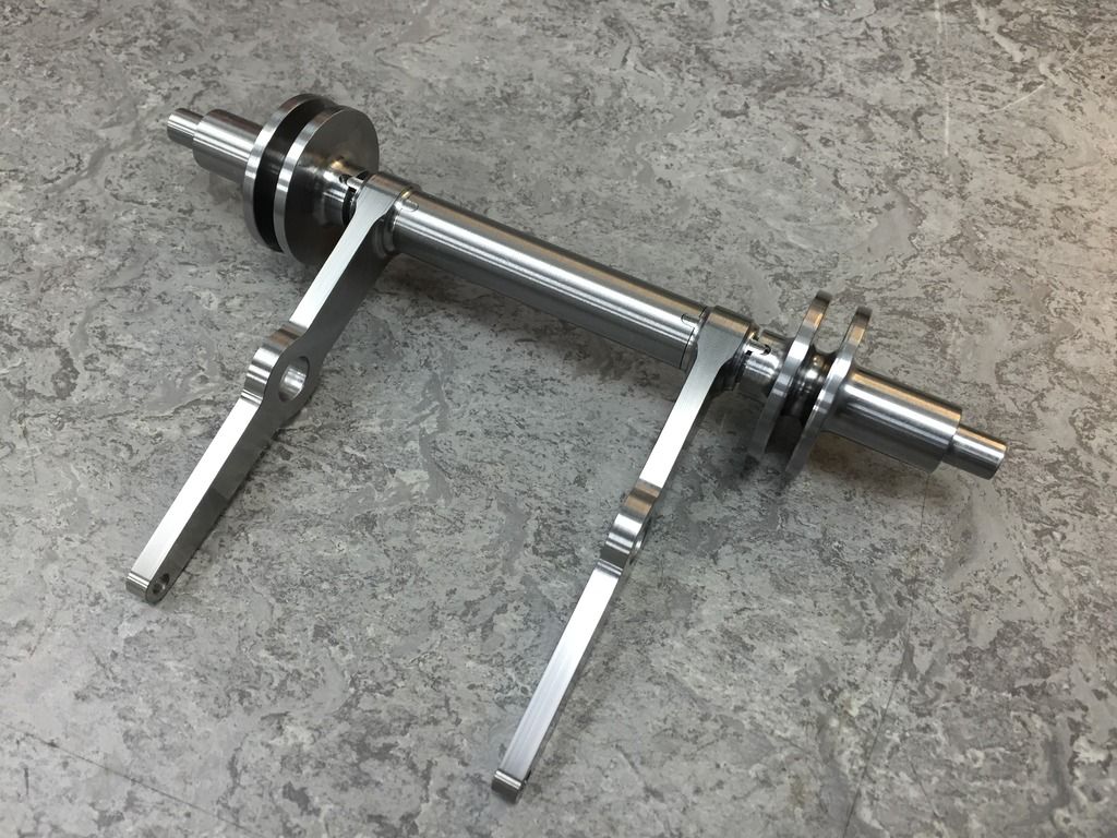 |
|
pault
Elder Statesman
  
Posts: 1,502
|
Post by pault on May 15, 2015 20:02:47 GMT
I do like your way of "keying" the parts together Tim, nice thinking
|
|
|
|
Post by joanlluch on May 16, 2015 6:50:10 GMT
I do like your way of "keying" the parts together Tim, nice thinking Hi Paul, nice indeed, but an over-engineered solution if this was meant to be made for the real (I mean replicated), which of course is never the intention, and the reason why these kind of approaches are perfectly fine. |
|
|
|
Post by Roger on May 16, 2015 7:09:24 GMT
I do like your way of "keying" the parts together Tim, nice thinking Hi Paul, nice indeed, but an over-engineered solution if this was meant to be made for the real (I mean replicated), which of course is never the intention, and the reason why these kind of approaches are perfectly fine. That's the great thing about this hobby and having great equipment at your disposal, you can over engineer to your heart's content. I wouldn't over estimate the amount of time it takes to machine some of these features, it doesn't take that long to set up and do. For someone in your position though Joan, it's more cost and probably not an affordable approach. |
|
tim
E-xcellent poster
  
Posts: 236
|
Post by tim on May 16, 2015 7:42:35 GMT
I do like your way of "keying" the parts together Tim, nice thinking Thanks however I must confess it wasn't my idea,I was going to drill and pin the parts together but a work colleague suggested keying them and that seemed a better option to me. Tim. |
|
|
|
Post by joanlluch on May 16, 2015 7:58:10 GMT
Hi Paul, nice indeed, but an over-engineered solution if this was meant to be made for the real (I mean replicated), which of course is never the intention, and the reason why these kind of approaches are perfectly fine. That's the great thing about this hobby and having great equipment at your disposal, you can over engineer to your heart's content. I wouldn't over estimate the amount of time it takes to machine some of these features, it doesn't take that long to set up and do. For someone in your position though Joan, it's more cost and probably not an affordable approach. Hi Roger, you know about me and which are my skills. I don't want to enter into a general discussion on that one once more, but I just would be happier if more people would be able to "open" the scope of the hobby to something more than mechanical milling craftsmanship. At best, this is very restricting. The forums have reduced down to just that in the last couple of months. The disappearance of very knowledgeable members and the reduction of posts covering theory or technical subjects does not help to improve on the current situation, which also includes my renounce to post in my own build thread due to general lack of interest. |
|
tim
E-xcellent poster
  
Posts: 236
|
Post by tim on Jul 18, 2015 20:24:46 GMT
Hi all, so a long overdue update. Firstly the finished brake shaft and its trunnions are now complete, 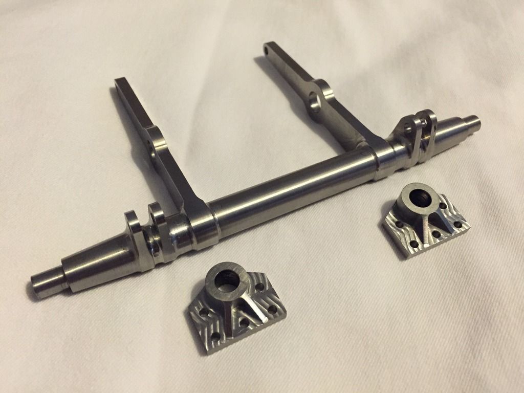 and next up I`ve decided to make a start on the little oil trays that sit in the bottom of the axleboxes. There are 10 of these in total, and in three different sizes, 2 of which are for the tender and the largest pair for the cartazzi boxes. Also since there is much to do to them I felt it wise to knock up an aluminium one of each size for setting up purposes. Also I made three sized blocks that fit snugly in the oil tray pockets to save from crushing whilst holding in a vice. 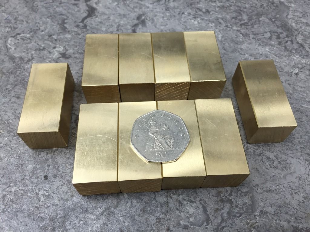 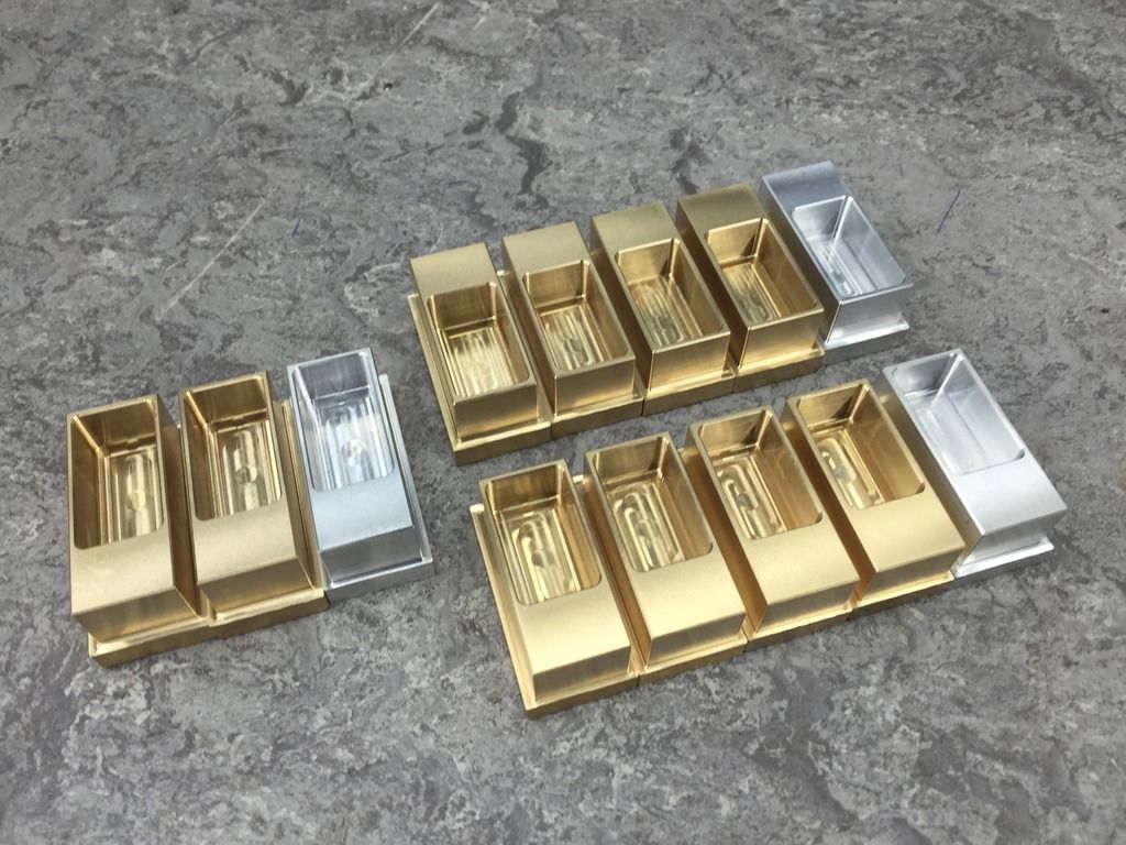 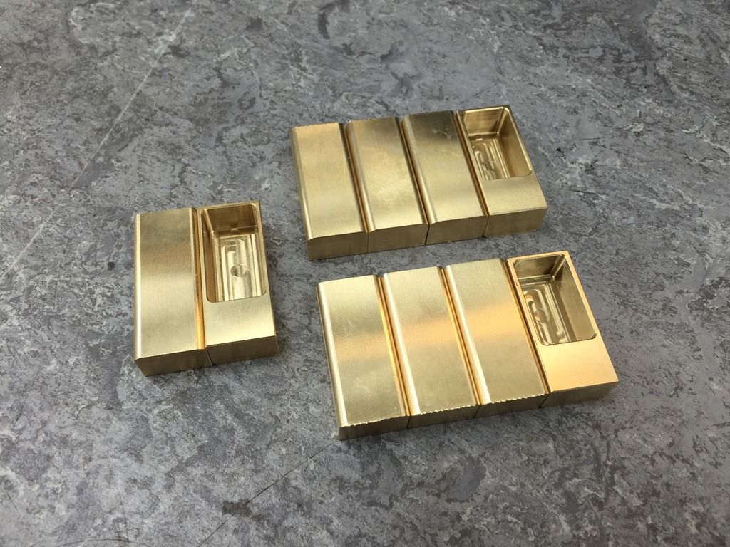 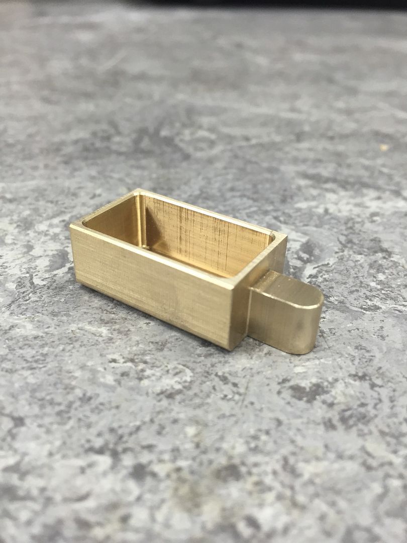 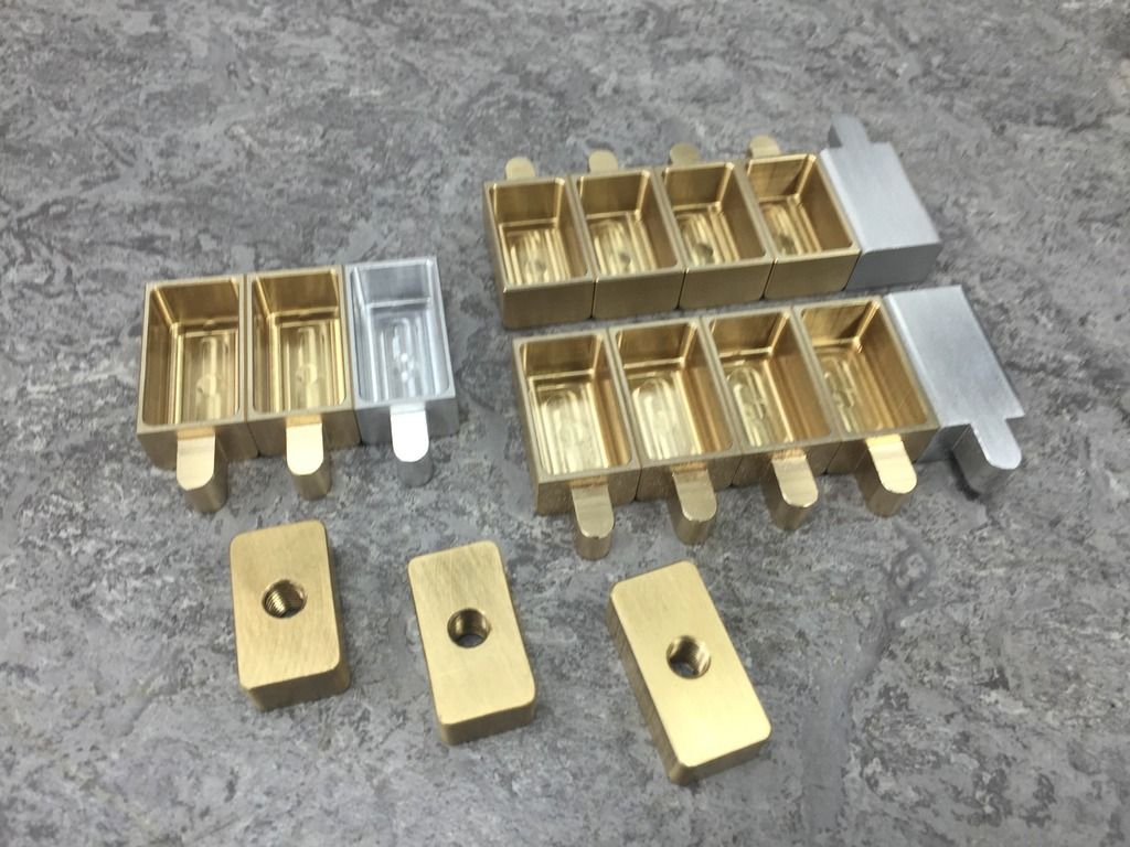 These still need quite a lot doing to them so more to come. Tim. |
|
tim
E-xcellent poster
  
Posts: 236
|
Post by tim on Sept 24, 2015 11:09:14 GMT
So I've decided to stray slightly from the drawings now and make these more like Mallards tender, since I have a lot of close up photos of it and therefore is an easy reference. The Plan...  Next then, it was on to an angled tipping vice where I needed to drill all the way through to the oil compartment. This hole was to be plugged off at the front so I made a small counterbore to be a snug fit on some 3mm brass plugs. Which I then added loctite to and tapped them in and peened them over. 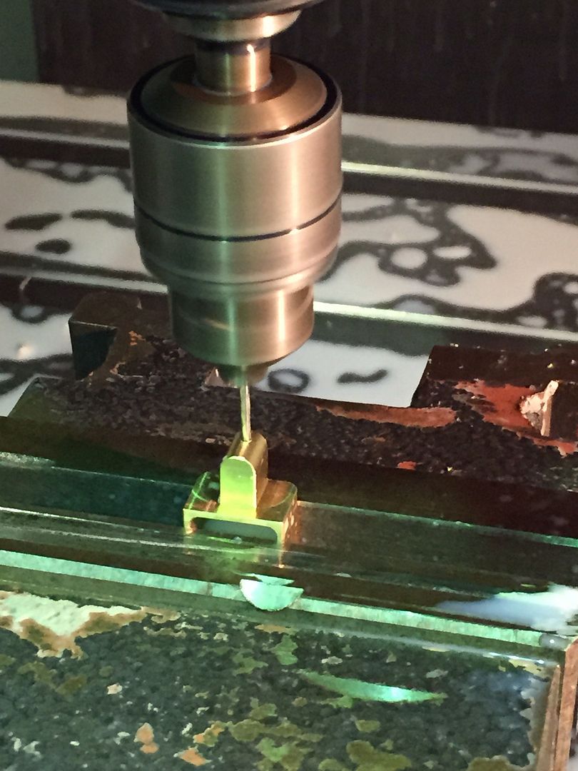  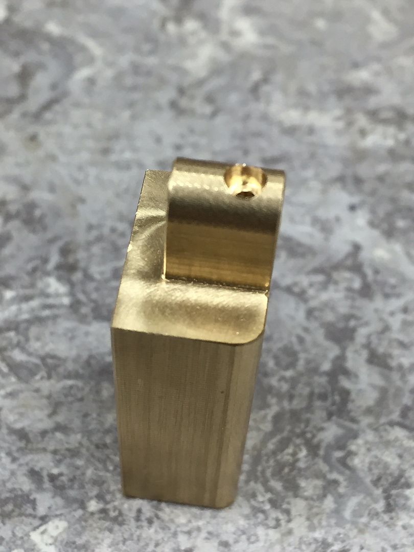  Once that was done I then machined some of the profile whilst at the same time cleaning up the front edge to remove the excess plug material. Unfortunately two of the plugs came out during this stage, both of which I hadn't used loctite on hoping that the light tap fit would be enough to hold them but I recovered them and put them in again this time with loctite. 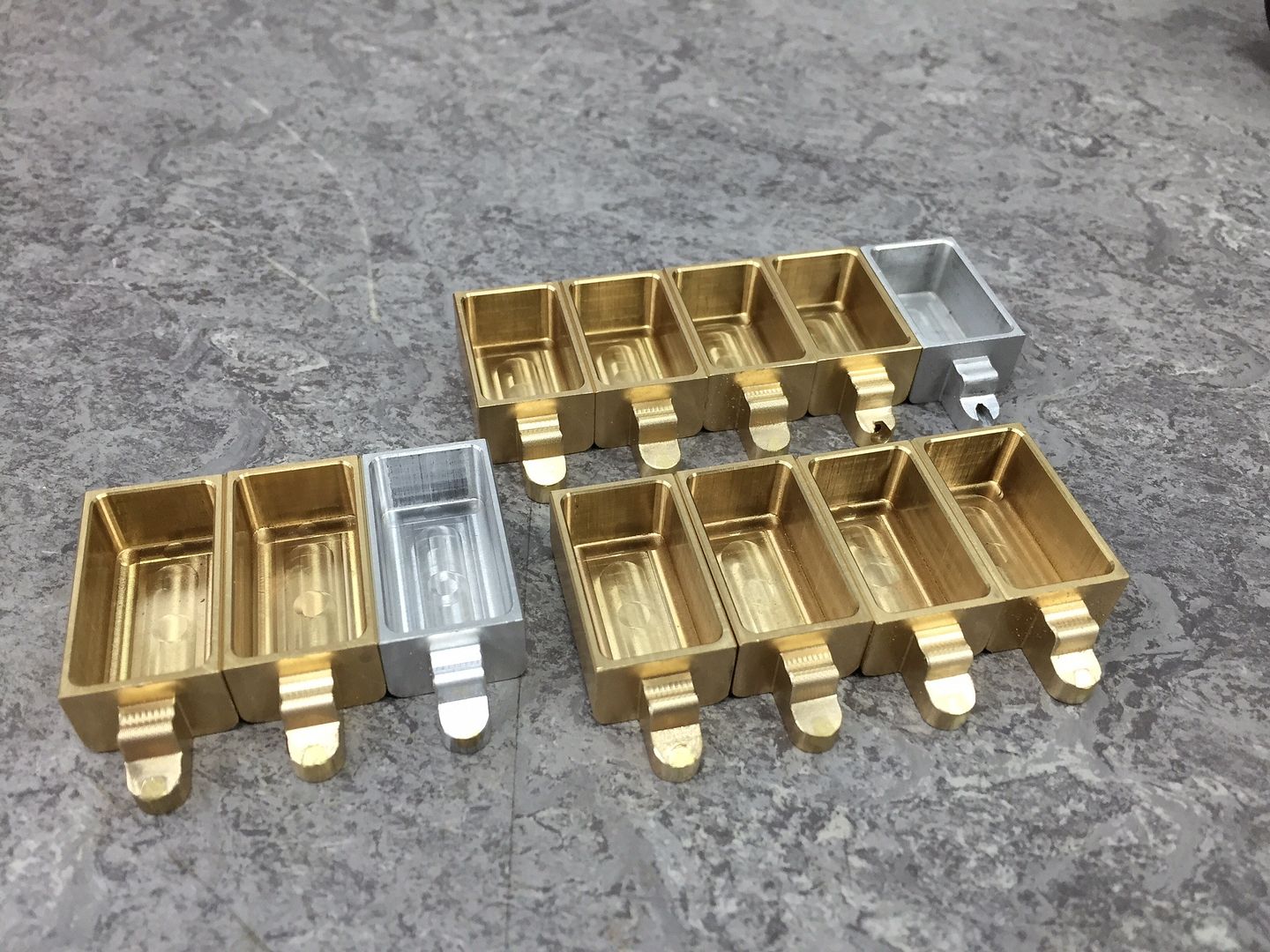 More soon, Tim. |
|
tim
E-xcellent poster
  
Posts: 236
|
Post by tim on Sept 25, 2015 8:18:01 GMT
Continuing on, the end detail is finished now, just requiring the hinged lid to complete, and a scollop in the back edge to clear the axle. Oh and I gave them all a quick blast in the sandblaster to even the finish up a bit. 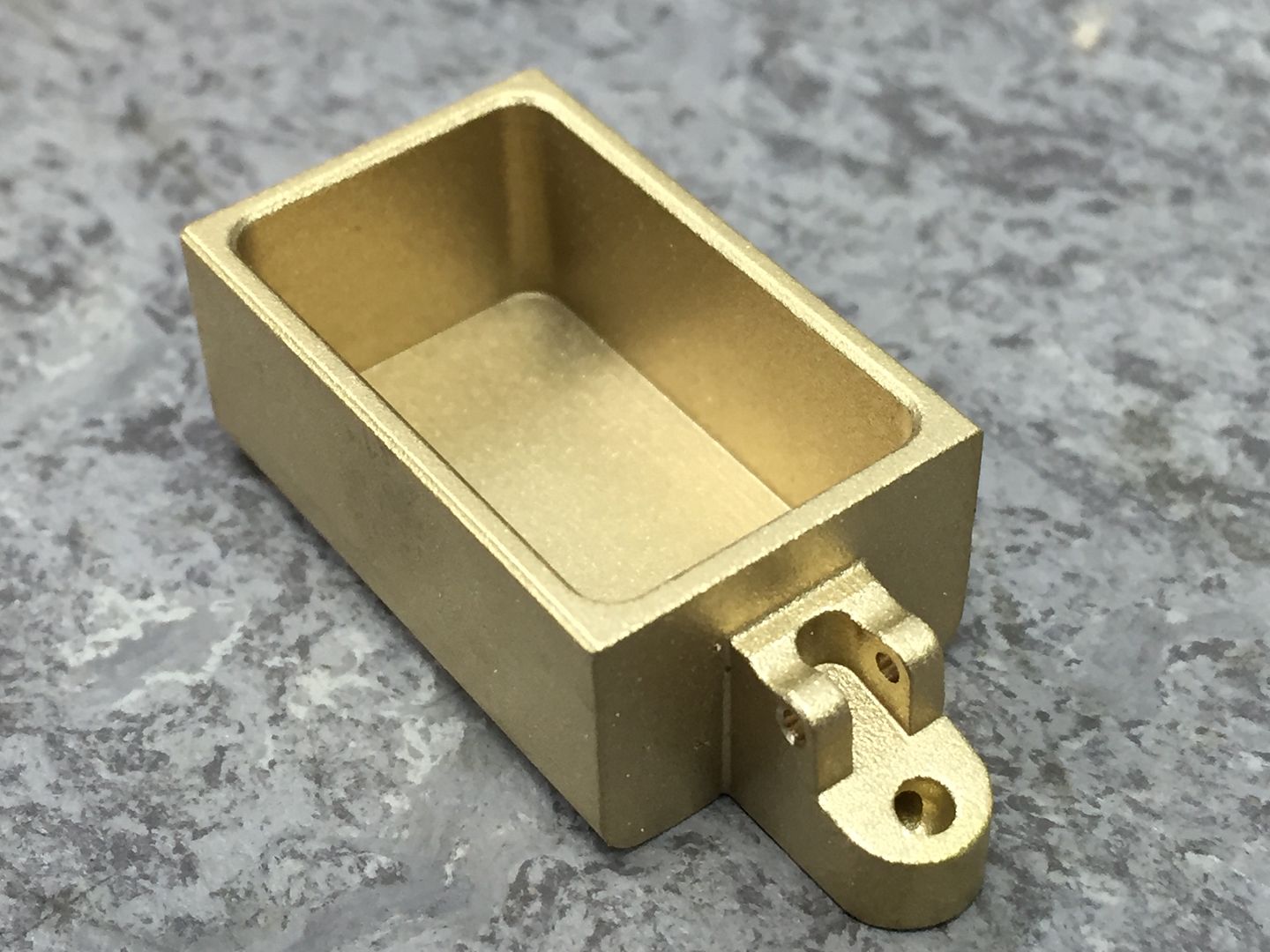 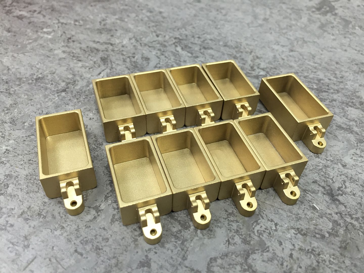 Hopefully more soon. Tim. |
|
|
|
Post by Deleted on Sept 25, 2015 8:32:38 GMT
lovely work Tim....looking great
Pete
|
|
tim
E-xcellent poster
  
Posts: 236
|
Post by tim on Sept 26, 2015 15:08:14 GMT
So some more progress today, the axle box covers are now complete. Must be on a roll! Tim. 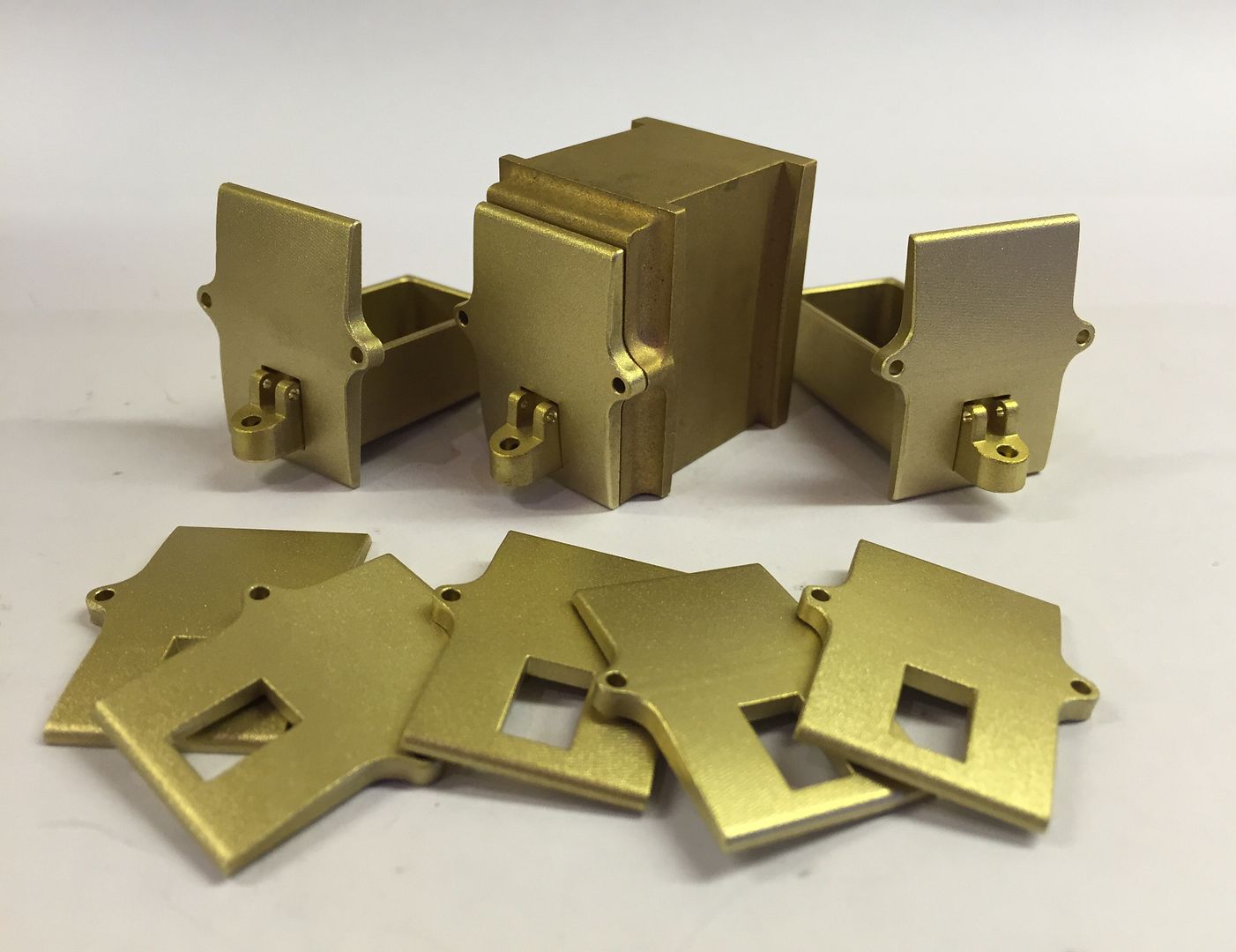 |
|