|
|
Post by Roger on May 24, 2014 18:09:52 GMT
Before I met SWMBO I had an Emco compact 5 CNC lathe in my sitting room. It was made very clear that the lathe was not welcome when I moved in with her Women can be so unreasonable. |
|
|
|
Post by Doug on May 25, 2014 18:02:55 GMT
Ok been busy getting the mill moved to the new stand 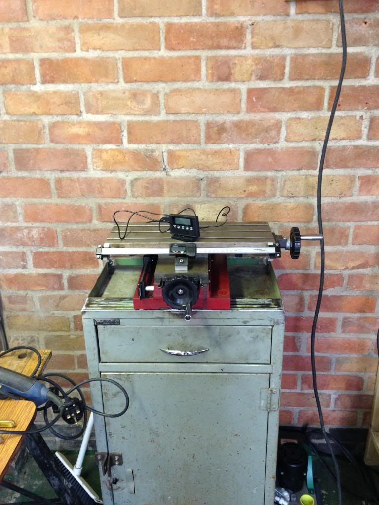 Fitted the drip tray and the coolant pump and tank righthand side the pc has a home too now, I am going to fit the box with the drives on the other side to protect the pc and breakout board from the electrical noise of the drives 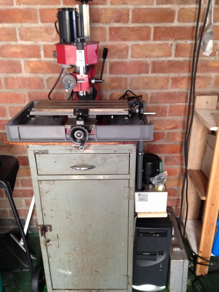 The guarding can be easily added to to stop the swarf however I will hold off doing anything with this till I have completed the fitting of the motors |
|
|
|
Post by Roger on May 26, 2014 8:40:20 GMT
That's a really good start, and reminds me to get dressed and out there doing something useful.
|
|
|
|
Post by Doug on May 28, 2014 5:48:33 GMT
Ok more parts ordered today I have the motors (3Nm steppers) on order and 3off 5Amp drives so I can get started when it all arrives. still on the shopping list,
1off pc monitor
3off lead screws
3 off bearings for lead screws
3 off Oldham couplings
1 off MPG
non of the above should stop me getting set up though so once it all arrives I can make a good start the long lead delivery is at least giving me time to fix my welder
|
|
|
|
Post by Roger on May 28, 2014 6:12:49 GMT
Here are a few places to get some of that from. you probably know of them, but just in case you don't...
hpc gears
automotionmoore
I generally use simply bearings for the incidental stuff like bearings, they tend to be cheap but good quality. |
|
|
|
Post by Doug on May 28, 2014 7:03:21 GMT
on a bit of a side note I thought i would post some pic's of the progress on the welder not exactly a rolls royce finish on the paint but its a welder! before 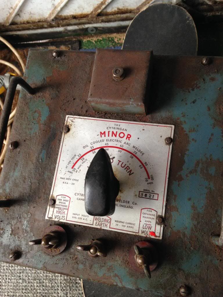 After/ half way through 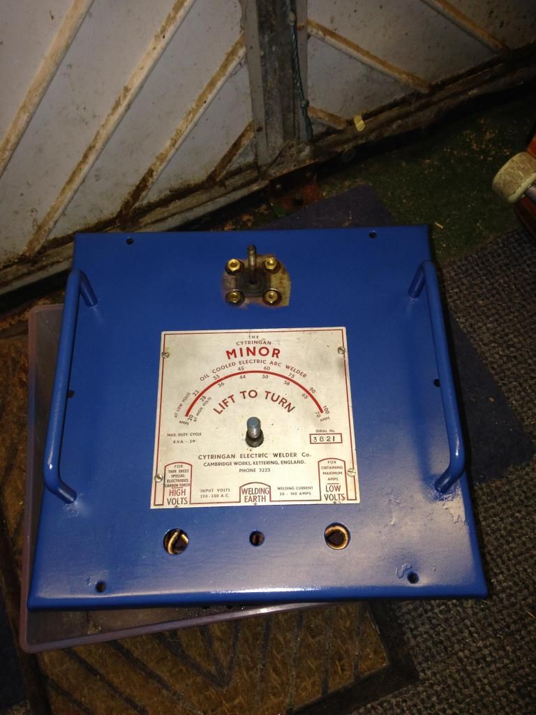 just got the box to strip and paint then its time to refill with the new dilectric and put all the fixings back on then use the welder to make a trolly 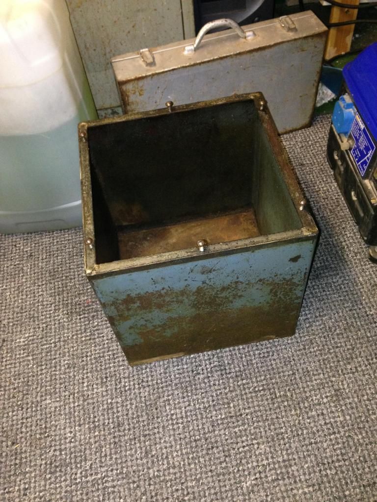  |
|
|
|
Post by Roger on May 28, 2014 8:22:56 GMT
That's a bit better. I think this is the type we used in the apprentice centre, built like a brick outhouse.
|
|
|
|
Post by cplmickey on May 29, 2014 11:52:19 GMT
Some useful links there Roger. Thanks for those.
|
|
|
|
Post by Doug on May 29, 2014 12:17:37 GMT
while i await the delivery of all my bits i decided to do a bit of experimnting with G code programming, so here it is so far (I obviously dont know if what i am doing is correct so any input is welcome) i normally fix/build machines not run them  first off i started with the part i want to make the exhaust flange for the blast pipe i then used Autocad to make a .DXF file using a polyline as the outside 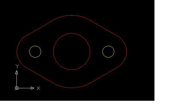 i then used CamBam to generate two programs OP1 to drill the two 4mm holes in yellow "Simples" then again OP2 to make the 1/2" hole in the middle and to profile the outer edge "part on a stick style" with tabs to break off later. I then used a simulator to check it all works 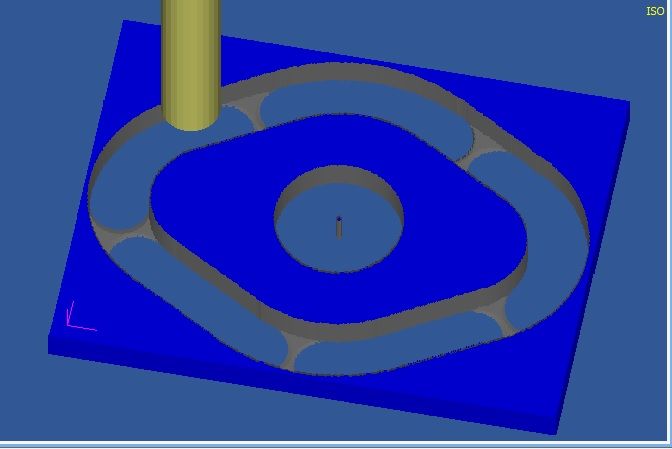 it all looks ok i think. The main reason for using two programs is the tool change. I can drill the small holes with a drill bit but the larger one and profile can use a 6mm cutter. so if the above part was real it would already have the small holes in it. regards, doug |
|
uuu
Elder Statesman
   your message here...
Posts: 2,860
|
Post by uuu on May 29, 2014 12:50:21 GMT
I might have programmed a third small hole in the middle, so the milling cutter is then profiling rather than slotting.
|
|
|
|
Post by Roger on May 29, 2014 13:32:14 GMT
That all looks plausible. I agree that you want to machine all of the material in the centre hole away. You'll find that anything that's left in the middle has a tendency to jam against the cutter when it breaks free.
CAM programs use a 2D entry to minimise the damage done during a plunge into the material. That always leaves a witness if you just plunge.
Personally, I don't use tabs any more. The problem is that you have to plunge straight into the material, and cutters don't like that. You have to leave a fair sized tab to make it strong enough to resist the cutting forces so they have to be quite wide and thick. I find it more convenient to forget about tabs, use a 3D entry when roughing and then a very short 2D entry on finishing, plunging into the roughed slot.
That way you get the job held firmly, very few blemishes on the profile and it's no great effort to cut through the last bit by hand and tidy it up with a file.
You'll always need a roughing and a finishing cut. I leave about 0.3mm to clean up with.
Anyway, you'll find your own methods that work for you, holding the part and deciding the entry method are the key decisions you have to make on these parts.
For something like your job, you could machine the two holes first and use those to clamp down the part from the inside. I've used that many times, but I still think it's quicker to use the 'part held by a wafer' method because there's no faffing about with fixing bolts and making sure there are clearances over them. You can also machine the whole lot in one operation without tool changes.
I was put onto this by an old hand and I resisted it at first. I came round to his thinking in the end though for most sheet or plate parts.
|
|
uuu
Elder Statesman
   your message here...
Posts: 2,860
|
Post by uuu on May 29, 2014 13:40:57 GMT
CamBam is quite good at tabs - it ramps up and down to create them rather than plunging - but yes, the material breaks away if they're not big enough. I tend to cut right through, and have not had problems - but I'm usually on hand to check.
Wilf
|
|
uuu
Elder Statesman
   your message here...
Posts: 2,860
|
Post by uuu on May 29, 2014 13:51:44 GMT
I quite like to use Mach3 as my simulator. It has a visualisation of the cutting path that you swivel about in 3D to look from all directions - and check that you're lifting over, not crashing through where you fast-track between profiles. And a display of the max and min values of XYZ, so you can confim you haven't any unexpected excursions into the greenery. And an estimator for program run time. What it lacks is an image of the parent material or cutter width, so you have to imagine those.
Wilf
|
|
|
|
Post by Doug on May 29, 2014 14:05:50 GMT
That all looks plausible. I agree that you want to machine all of the material in the centre hole away. You'll find that anything that's left in the middle has a tendency to jam against the cutter when it breaks free. CAM programs use a 2D entry to minimise the damage done during a plunge into the material. That always leaves a witness if you just plunge. Personally, I don't use tabs any more. The problem is that you have to plunge straight into the material, and cutters don't like that. You have to leave a fair sized tab to make it strong enough to resist the cutting forces so they have to be quite wide and thick. I find it more convenient to forget about tabs, use a 3D entry when roughing and then a very short 2D entry on finishing, plunging into the roughed slot. That way you get the job held firmly, very few blemishes on the profile and it's no great effort to cut through the last bit by hand and tidy it up with a file. You'll always need a roughing and a finishing cut. I leave about 0.3mm to clean up with. Anyway, you'll find your own methods that work for you, holding the part and deciding the entry method are the key decisions you have to make on these parts. For something like your job, you could machine the two holes first and use those to clamp down the part from the inside. I've used that many times, but I still think it's quicker to use the 'part held by a wafer' method because there's no faffing about with fixing bolts and making sure there are clearances over them. You can also machine the whole lot in one operation without tool changes. I was put onto this by an old hand and I resisted it at first. I came round to his thinking in the end though for most sheet or plate parts. i like the idea of leaving the whole lot round the edge just saw the tabs (auto generated) and thought hey why not how much do you leave thickness of the plate? |
|
|
|
Post by Doug on May 29, 2014 14:10:52 GMT
I quite like to use Mach3 as my simulator. It has a visualisation of the cutting path that you swivel about in 3D to look from all directions - and check that you're lifting over, not crashing through where you fast-track between profiles. And a display of the max and min values of XYZ, so you can confim you haven't any unexpected excursions into the greenery. And an estimator for program run time. What it lacks is an image of the parent material or cutter width, so you have to imagine those. Wilf i used cut viewer mill for the simulation it adds the parent materal and the cutters so you can see the whole thing i quite like the software as it lets you look at the finished part and it also lets you know if you being a super hero with your feeds on the cutters. |
|
uuu
Elder Statesman
   your message here...
Posts: 2,860
|
Post by uuu on May 29, 2014 14:26:14 GMT
I'll give that one a try.
|
|
|
|
Post by Roger on May 29, 2014 14:29:48 GMT
CamBam is quite good at tabs - it ramps up and down to create them rather than plunging - but yes, the material breaks away if they're not big enough. I tend to cut right through, and have not had problems - but I'm usually on hand to check. Wilf That's neat, I'll take another look at my CAM output but I think it only plunges, which to my mind is hopeless. I'd be inclined to give them another try if that option is available |
|
|
|
Post by Roger on May 29, 2014 14:32:18 GMT
i like the idea of leaving the whole lot round the edge just saw the tabs (auto generated) and thought hey why not how much do you leave thickness of the plate? It varies depending on how big the cuts are, but 0.5mm is a good place to start. It can be a bit variable if you're using sheet and it's not held down flat. I've been known to move the quill up a bit while it's cutting if it looks like it's going to break through. |
|
|
|
Post by Roger on May 29, 2014 14:35:16 GMT
I quite like to use Mach3 as my simulator. It has a visualisation of the cutting path that you swivel about in 3D to look from all directions - and check that you're lifting over, not crashing through where you fast-track between profiles. And a display of the max and min values of XYZ, so you can confim you haven't any unexpected excursions into the greenery. And an estimator for program run time. What it lacks is an image of the parent material or cutter width, so you have to imagine those. Wilf i used cut viewer mill for the simulation it adds the parent materal and the cutters so you can see the whole thing i quite like the software as it lets you look at the finished part and it also lets you know if you being a super hero with your feeds on the cutters. My CAM software does the 3D simulation too, but I'll certainly look at what Mach3 has to offer as another sanity check. Sometimes the view van be a little cluttered on the CAM whereas Mach3 will only have the one path to show. I've just got the SmoothStepper in the post today so I'll have to work out how I'm going to interface it into what's already there. It should be interesting. I'll start another thread on that when I get going on it. |
|
|
|
Post by Doug on May 29, 2014 14:57:56 GMT
i used cut viewer mill for the simulation it adds the parent materal and the cutters so you can see the whole thing i quite like the software as it lets you look at the finished part and it also lets you know if you being a super hero with your feeds on the cutters. My CAM software does the 3D simulation too, but I'll certainly look at what Mach3 has to offer as another sanity check. Sometimes the view van be a little cluttered on the CAM whereas Mach3 will only have the one path to show. I've just got the SmoothStepper in the post today so I'll have to work out how I'm going to interface it into what's already there. It should be interesting. I'll start another thread on that when I get going on it. here is the link to the viewer site its alot better than mach3 as it has alot more to offer! Cut Viewer Mill they do a free trial try it out with a working Gcode program its actually quite good |
|