|
|
Post by Doug on Jun 3, 2014 15:05:24 GMT
right quite luckily the decission has been made regarding the lead screws its going to be a two stage setup to get me going i am going to use the delrin nuts and m10 threaded rod the motor mounts may well be made out of wood for the time being as i have two out of the three ballscrews lined up for stage two.
why mess about you may ask? well the z axis ballscrew is going to need some major fabrication work (ideal for a CNC machine) the y axis will need some work and all three will need some motor mounts making again a nice job for a CNC machine, i could make all these bits manually but it will take forever at the pace my mill cuts 5 hours of cutting is about three weeks work for me in my spare time so not ideal. i have just bought a monitor for 99p which is nice so just the drives to come and i can get set up.
|
|
|
|
Post by Roger on Jun 3, 2014 15:59:22 GMT
I really like this plan, lash up the machine so it can make itself! Brilliant! You'll easily get the accuracy you need from doing it that way. A nice piece of lateral thinking.
|
|
|
|
Post by Doug on Jun 5, 2014 12:05:14 GMT
i am still furiously getting all my ducks in a row on this one the monitor and pc are alltested and working i now have a complete z axis ball screw and a y axis ball screw the x axis is a lot more problematic in that its not got much wiggle room in there (about 20mm) so large ballscrews of which are easy to come by wont fit. i am still waiting for my delrin nuts a bag full of 6200 bearings for the lead screws and an MPG as well as the drives not too long to wait i hope
|
|
|
|
Post by Roger on Jun 5, 2014 12:52:04 GMT
Room is an issue on all machines designed for manual use I'm afraid. I managed to shoehorn mine in but the choice of leadscrew was very limited. I have to take an angle grinder to part of the nut housing because there was no way it would fit otherwise.
|
|
|
|
Post by Doug on Jun 9, 2014 18:50:15 GMT
Some small progress my drive came today so I quickly rigged up the x axis motor to try it out and it works fine, noticed that too much rapid movement results in the motor stalling once I slowed the velocity down it kept up very well just got to get a few more parts then I can put it all together, at least now I can wire it all up.
|
|
|
|
Post by Doug on Jun 16, 2014 19:07:06 GMT
Time to get building first off is strip the machine down err check 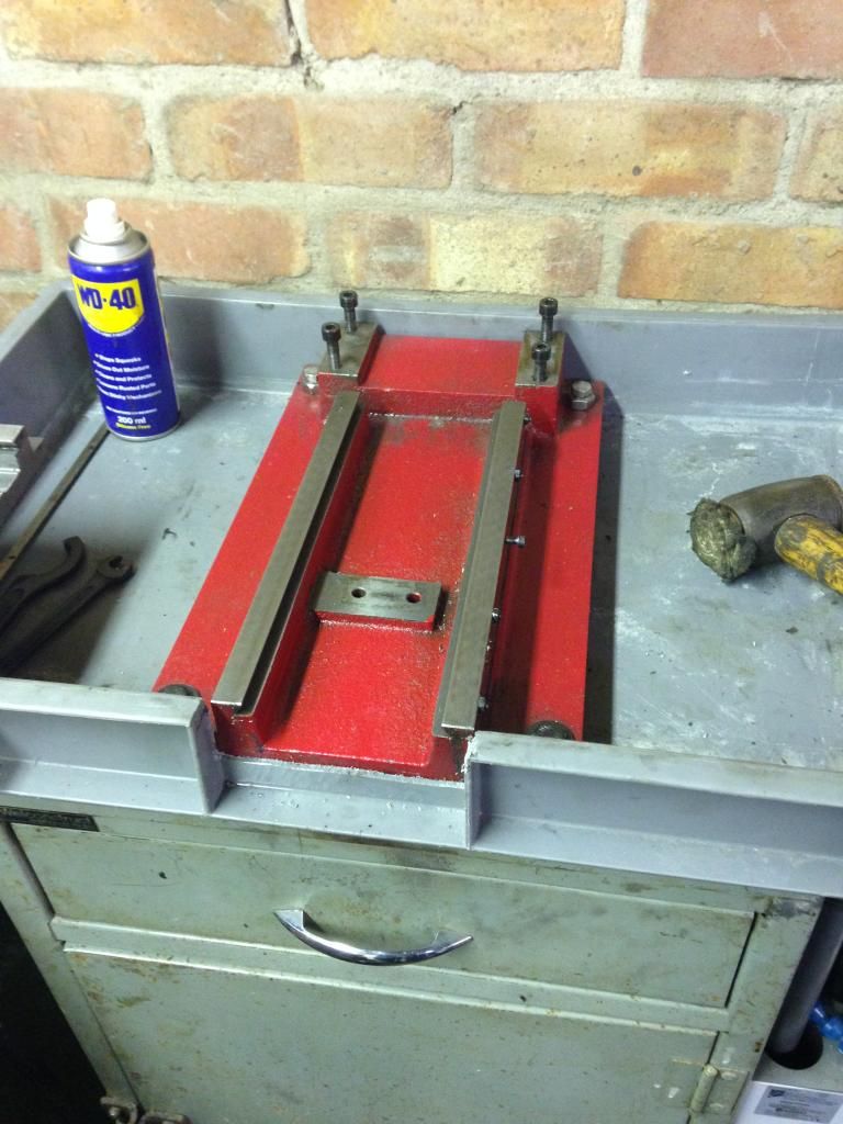 Y axis to get done first I have got to make some bearing blocks first got quite a bit of head scratching ahead of me |
|
|
|
Post by Doug on Jun 18, 2014 20:49:43 GMT
I am still on a mission to get this done although hey fever is knocking the stuffing (and enthusiasm) out of me at the mo I am however making slow steady progress y axis is nearly done 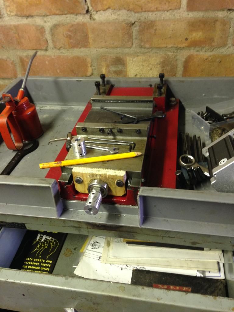 The lead screw is in and has zero backlash thanks to the delrin nut two deep groove bearings keep the screw from slopping I am as I go designing and making the g code program's to replace the temporary end plates and motor mounts so once built it's first job will be to make the proper kit the end plate in the pic has a machining time of 4:35 hours:mins so should be quite a work out. |
|
|
|
Post by Roger on Jun 19, 2014 21:01:36 GMT
Excellent, and I love the wooden end plate, great lateral thinking.
I'm curious to know why the run time of the end plates is so long? Are you 3D machining the whole thing including the face?
This may be a good time to give a ripper a try. I know they're expensive but when you've got a lot of metal to remove they're probably the best cutter for the job. What's the optimum cutter size for your machine when you're profiling to those sort of depths. I tend to use 6mm diameter on mine when I'm profiling something out of a solid piece. For me it's a reasonable compromise in terms of stiffness while not removing any more material than absolutely necessary. I take it slowly and I'm not too greedy on the depth of each cut, say 3mm deep.
|
|
|
|
Post by Doug on Jun 20, 2014 9:26:43 GMT
Excellent, and I love the wooden end plate, great lateral thinking. I'm curious to know why the run time of the end plates is so long? Are you 3D machining the whole thing including the face? This may be a good time to give a ripper a try. I know they're expensive but when you've got a lot of metal to remove they're probably the best cutter for the job. What's the optimum cutter size for your machine when you're profiling to those sort of depths. I tend to use 6mm diameter on mine when I'm profiling something out of a solid piece. For me it's a reasonable compromise in terms of stiffness while not removing any more material than absolutely necessary. I take it slowly and I'm not too greedy on the depth of each cut, say 3mm deep. right o look like i may be being way too steady i was taking 0.4mm off each cut (experiance from cutting manually) I will get it all together and see how it cuts i have setup a 6mm cutter in the program as anything much bigger diameter can cause diffelction of the head. The 6mm cutter runs like a hot knife through butter and i could prob. cut about 1-1.5mm but i will have to check once built. I am making the end plates from 10mm aluminium with a pocket 7mm deep for the bearing i have given it a good clearance of 0.1mm though so it will allow a small amount of play when setting it up. I really need to get moving as all my parts have arrived now incluiding the same MPG that you ordered. the only thing stopping me is hayfever though i am finding it very dificult to function at the moment let alone make time to build my machine up. only a couple more weeks and it will be a distant memory and i can get on with enjoying the summer. |
|
|
|
Post by Roger on Jun 20, 2014 10:58:39 GMT
On my CAM program, it defaults to using a very conservative overlap when pocketing and that takes a long time. I like to cut at least 2/3 of the cutter diameter on operations like that. It's also not always quickest to zip round taking small cuts, slower deeper cuts suits my machine better and removes the material more quickly using more of the cutters edge length. It's definitely worth experimenting with.
|
|
|
|
Post by Doug on Jun 20, 2014 19:39:39 GMT
Some steady yet slow progress the y axis is done 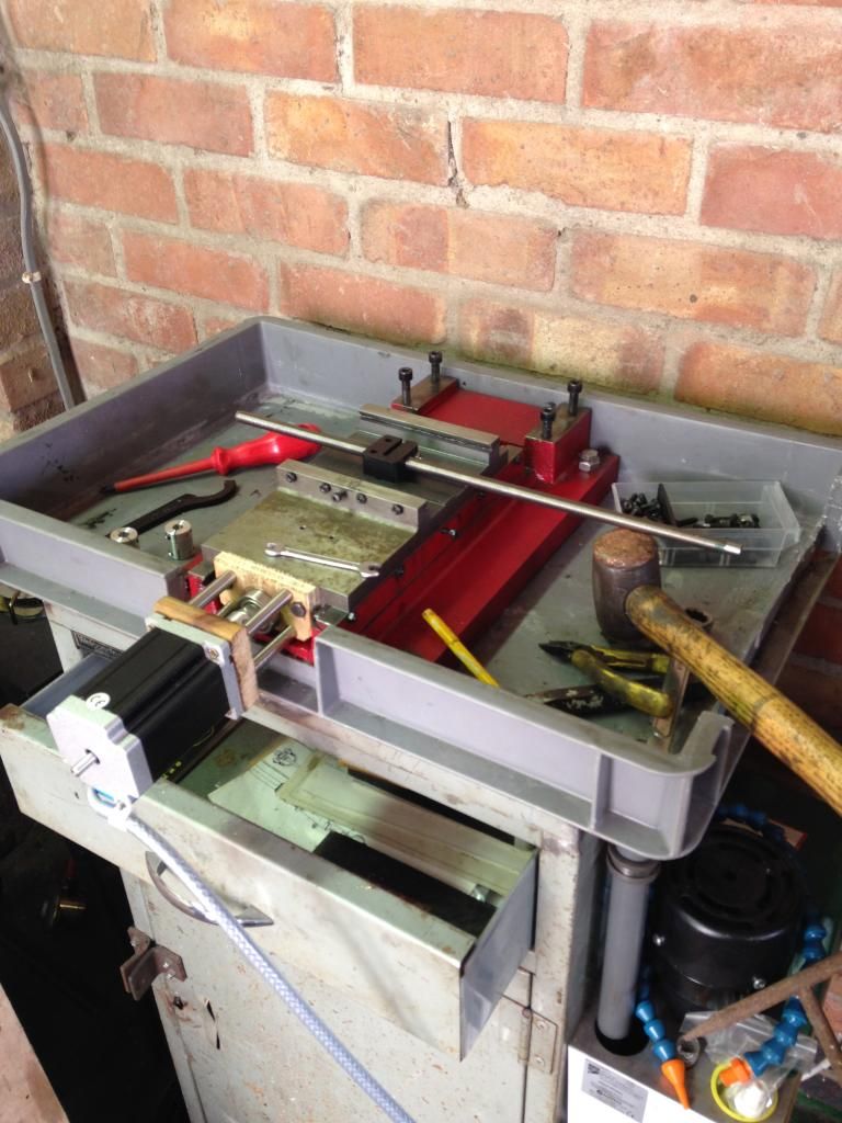 And I have also got the MPG tested and working x axis is next up, this will be quite simple one end plate this time and the motor mounted the same way as the y axis |
|
|
|
Post by Roger on Jun 20, 2014 21:43:38 GMT
Good work, made all the easier by the use of a precision mallet.
That's quite a sturdy little machine really, there's quite a lot of metal in those castings.
|
|
|
|
Post by Doug on Jun 21, 2014 19:20:08 GMT
I had a good day at fitting lead screws and motors just have the z axis to finish off and I can get the machine to make its motor mounts out of aluminium 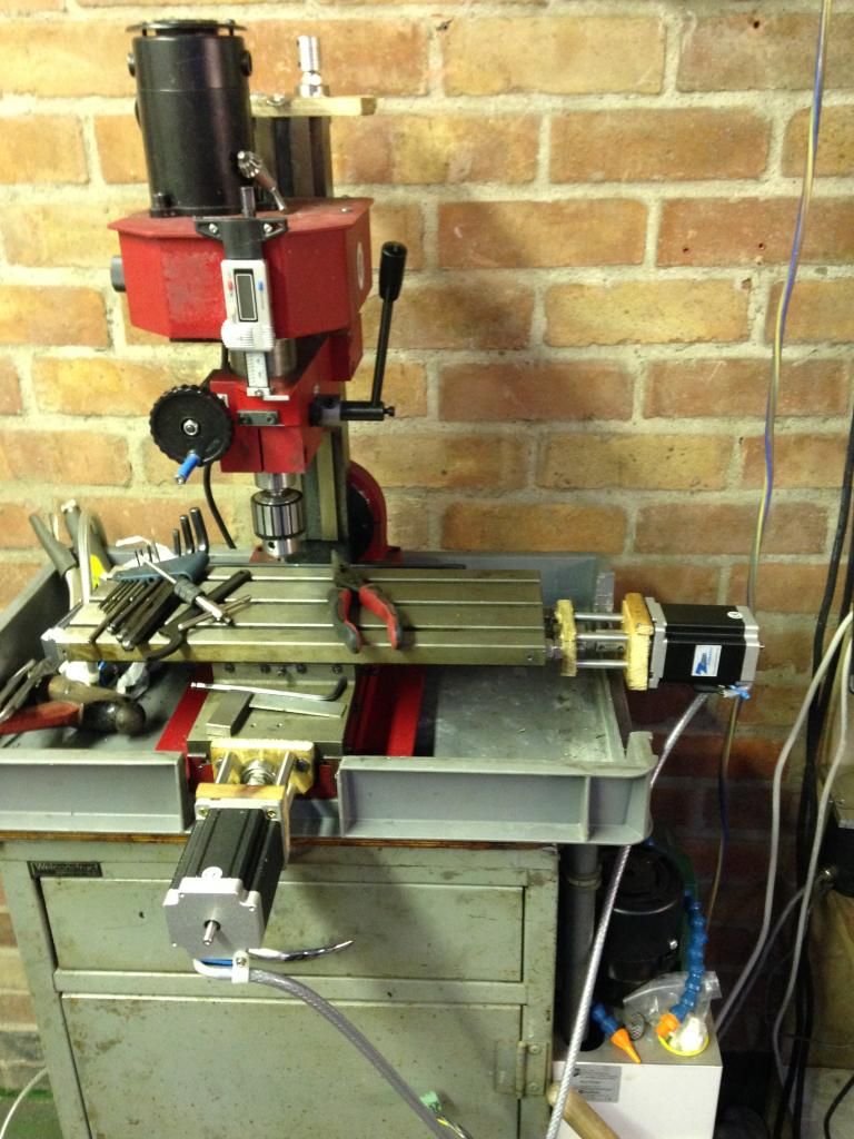 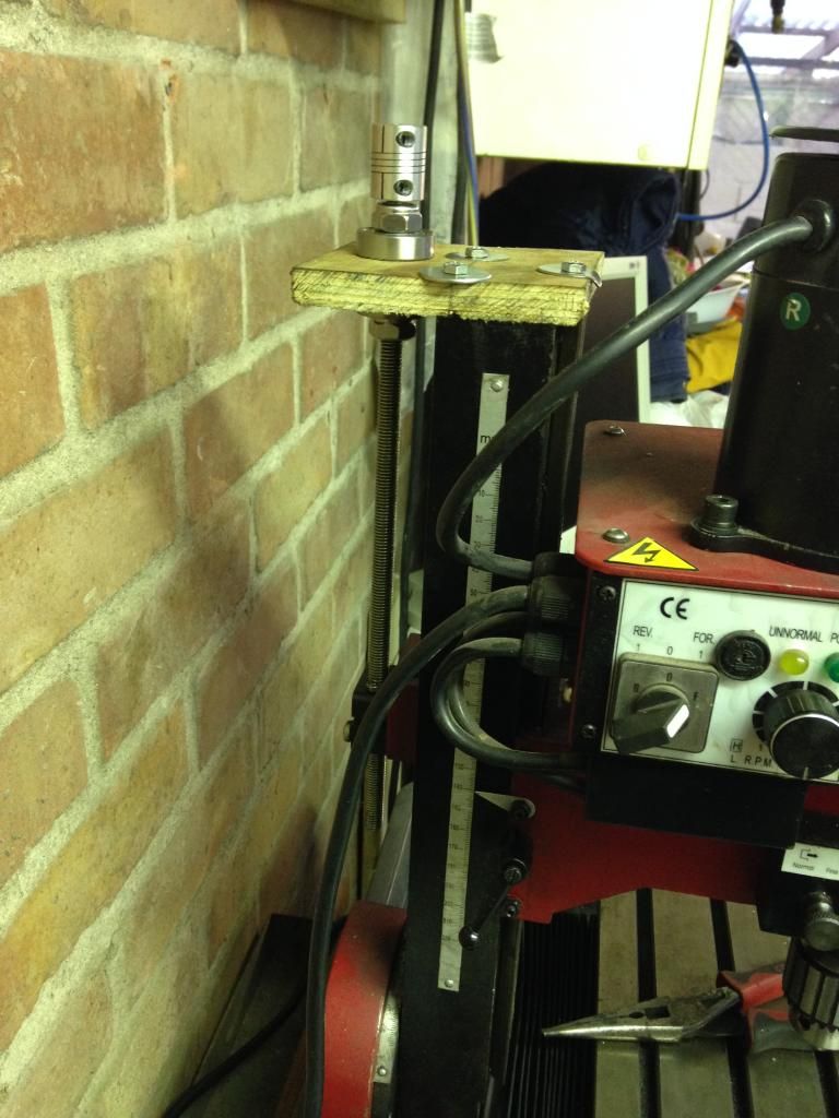 |
|
|
|
Post by Roger on Jun 21, 2014 21:06:12 GMT
Excellent, that's been a very productive day. You're going to love it when you get it working for the first time. Take a look at my latest post on my machine, you may want to do something similar to find out what backlash compensation you need to get the bearing pockets as round as possible.
|
|
uuu
Elder Statesman
   your message here...
Posts: 2,858
|
Post by uuu on Jun 22, 2014 7:48:01 GMT
Interesting thought, backlash compensation. I don't use it. I've never felt the need, and am quite happy with the finished dimensions, and roundness of pockets.
Aha! I hear you cry. But what if I have plain leadscrews, not ballscrews? My friend John's little mill has plain leadscrews, and I don't think he uses compensation either. No complaints from him or his customers.
So I'd give it a try without, and see how you get on. Cut some metal, and you'll get a feel for the machine and the tolerances it/you can work to. Then try and tweak it, only if youre not happy.
Wilf
|
|
|
|
Post by Roger on Jun 22, 2014 8:24:37 GMT
Well, I've been using it without since 2008 and I'm not happy with the results when really tight tolerances are required on things like bearing pockets. I gave up using it for those, favouring just roughing them on the mill and finish turning on the lathe. I suppose it all depends on your expectations. You can certainly make bearing pockets that seem to be good enough, but put a clock on the inside when they're done and you'll see that they are far from round.
I'd agree that for most things it doesn't matter, but I now have the facility to correct for it so I thought it made sense to get it as good as possible. I'd be surprised if any router had less than 20microns backlash so I reckon there's a lot to be gained from using it. I've got it set up to repeat pretty well on the following test so I think it's pretty close now.
Try clocking up a hole with a dial clock in the spindle nose, set the DROs to zero and then lift the Z without moving the clock, move to x1y1 then back to x0y0 and lower the head again. Note the readings and then repeat the exercise but go to x-1y-1 instead. I think you'll be surprised by the results.
I'm still talking to the developer of the CNCBrain that I've been using until recently and hoping that I can bin Mach3 in favour of something that can use my linear encoders. This is a definite improvement in terms of accuracy, but I'm not impressed by the user interface, I think it's flaky and unfriendly. I'm still grappling with the very painful process of customisation, the MPG interface it shockingly bad.
|
|
|
|
Post by Doug on Jun 22, 2014 16:09:22 GMT
Well I got it running very happy two trifling issues though the motors are getting a little hot and because of the odd way of mounting my motors I have a 30um of backlash on the x axis the y axis is totally free of lost motion so I will make the x axis motor and lead screw mounts first I don't expect to have any backlash once finished the delrin anti backlash nuts I have work very well indeed. 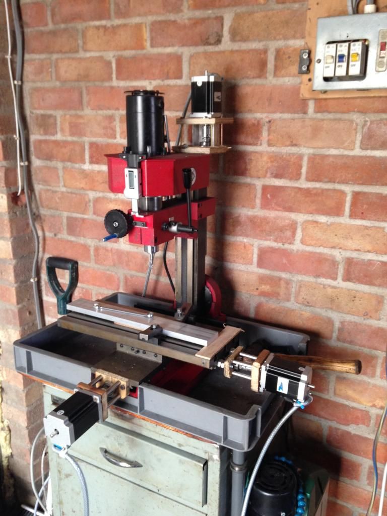 I will draw up the mounts tomorrow and machine them tomorrow night |
|
|
|
Post by Roger on Jun 22, 2014 17:52:28 GMT
Brilliant! That's huge progress, you must be delighted.
|
|
|
|
Post by Doug on Jun 22, 2014 18:56:46 GMT
Brilliant! That's huge progress, you must be delighted. Yes I am quite happy it has all come together really well I will be much happier once the motor and screw mounts are made as I have quite a lot of backlash I will finish off the bearing pockets with my boring head. I also need to refine the the safety circuit or what is described as a charge pump. I will (in line with normal machines) remove all power to the drives in an estop condition that should make sure it's nice and safe. The hot motors seem to have settled too I think it may have been a setting in the ports and pins page, to be safe I have limited the current to 3/4 of the motor rating so they should stay safe there is plenty of power anyway so I am really happy the performance will be good. |
|
|
|
Post by Roger on Jun 22, 2014 19:53:56 GMT
I'm pleased it's worked out so well, it's also confirmed the dimensions of the real parts you need to make by making the mock ups. Altogether a cute strategy and a real time saver. Other people contemplating a conversion would do well to copy this method.
|
|