|
|
Post by Doug on May 20, 2014 6:49:54 GMT
Hi as I have finally decided to take the plunge and convert my miller I thought I would write a thread on how I have done it and whats required incase anyone else wants to do it. my background is in maintenance and machine build "real CNC" so this is my first stepper drive build I personally am not a huge fan BUT it does give us normal motals the opatunity to use CNC without spending thousands. so first off my mill the sieg x1l is a very small very cheap machine it is not capable of doing large work. The base is not very stiff but if its used lightly it does a good job. I have modified it from standard already by adding digital scales and a power x axis feed all of which work very well. The reason for converting this mill is very simple, cost is very cheap indeed and when the size goes up the cost goes up massively and i am of the belief that it will do the job for me. so what have i got so far; 1 off old windows XP PC 1 off copy of Mach3 software 1 off 5v 30A power supply 1 off 24v 20A power supply 1 off steel enclosure (for the control boards and psu's) 1 off Sieg X1L miller I have ordered a breakout board and a 25 pin serial cable to get me started shoud be a couple of weeks delivery. the motors are 1.8Nm hybrid steppers for the x and y axis (not ordered yet) and i am looking at 2.2Nm hybrid stepper for the z axis (its got weight on it) i may have to make a counterbalence for this to make the weight neutral. I will be doing two jobs to get started modifying the miller, the spindle motor is currently 150W 240v DC motor I have a 250W DC motor and drive i want to fit that can be controled from the Mach3 software (the z axis may also get an upgrade to linear rails and ballscrew) and at the same time I want to get the PC breakout board system working before i buy expensive motors and drives. i am going to see how the leadscrews perform on the x,y axis while keeping an eye open for 8mm ballscrews (quite rare to find cheap) i may alter the leadscrew nuts to make them anti backlash for the time being. I will try and pop a picture of the machine up tonight. 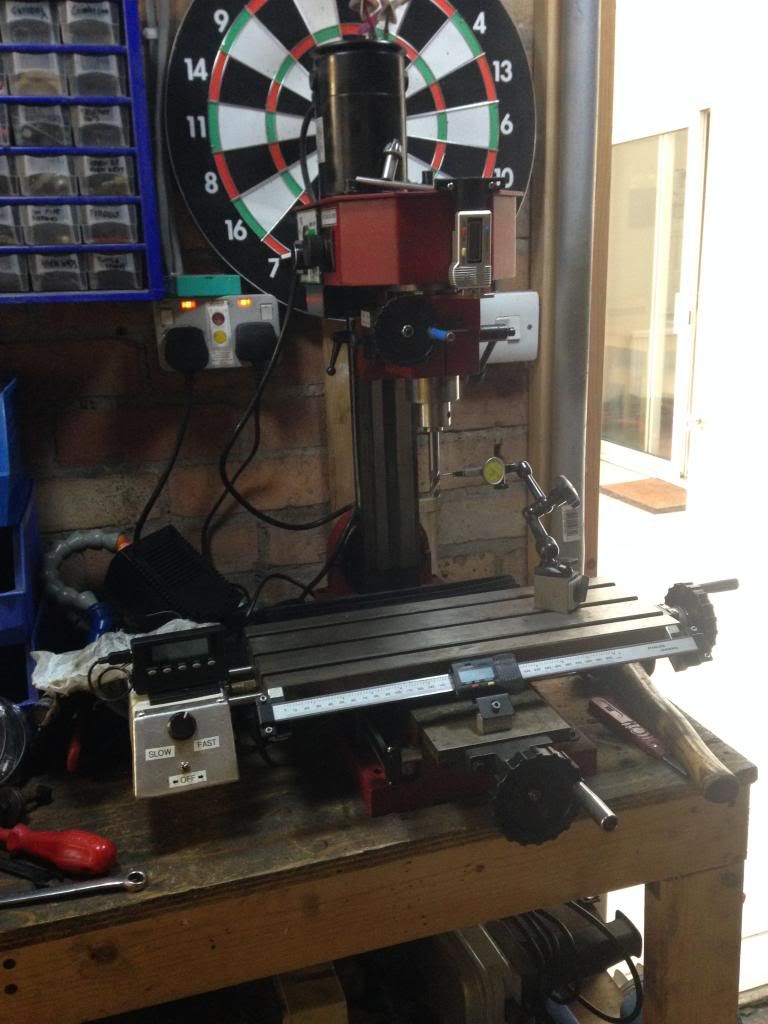 |
|
|
|
Post by Roger on May 20, 2014 15:26:54 GMT
It should be an interesting project, and show the way for others who are tempted to do the same but don't quite know how to go about it.
|
|
|
|
Post by Doug on May 21, 2014 9:29:39 GMT
Ok first off is the electrical drawing the breakout board is a standard Mach3 compatable board with all the bits i can think of that i want on it there are quite a few diferent types and you can add more to the PC if you want (you need to add another paralelle port to the pc if you do) i have decided to fit the switches in series so it saves inputs for other uses, and you can use a limit switch as a home switch as well (just goes to show how good the software is that it cna be configured this way) I have left the circuit deliberately simple so i can add bit as i find i need them alreeady thinking of airblast and coolant switching. I will connect it all up on the bench a test it out before modifying the mill. I have worked out that I wont need to micro step the drives which will improve the reliabilty i have 2mm pitch lead screws so with 200 steps per rev on a standard motor that gives me 0.01mm travel per step or 0.5 thou ish. it also looks like i need a counterbalence weight of around 8kg on the z axis that way i wont need a massive motor and drive (cost saving). all the nasty wiring on the X1 will be removed for this mod too which is good as I really dont like it at all. 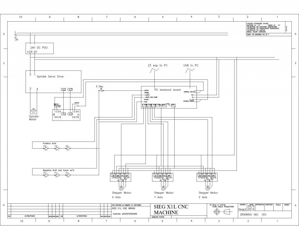 |
|
|
|
Post by AndrewP on May 21, 2014 10:46:57 GMT
I fitted a pair of gas struts to the Z on my X1 with a view to reducing the effort for the stepper in a future conversion, I used 70 N struts, 40 or 50 would have been sufficient, it is now easier to wind the head up than down  Andy |
|
uuu
Elder Statesman
   your message here...
Posts: 2,860
|
Post by uuu on May 21, 2014 11:37:40 GMT
I would recommend you do micro-step the drives. Not to chase after more resolution, because (as Roger tells people when they poke fun at him) microns are really small. But to get smoother running. I've got 10 micro-steps per full step (my Geckos are factory set like this), and Mach3 is quite happy firing off ten times the number of pulses, and I've not noticed any lack of reliability.
Some drivers will send a sinusoidal wave to the motors even if you're full-stepping, so you might be fine if you have these.
Wilf
|
|
uuu
Elder Statesman
   your message here...
Posts: 2,860
|
Post by uuu on May 21, 2014 11:42:24 GMT
I've fitted limit/home switches in series as you have, but at one end of each axis only. I found I had an electrical noise problem that tripped me up during running - so I "reference home" at the start of the run and then let Mach3 use "soft limits" to keep me from crashing either end during use.
Just for info - my little mill has a 370W 3-phase motor perched on its spindle - and a 180Ncm stepper is lifting this - with 2:1 belt drive.
Wilf
|
|
|
|
Post by Roger on May 21, 2014 15:02:38 GMT
Just one point, make sure that you only earth to a start point, and have only one place that 0v connects to it if you've referencing 0v to earth. Earth loops are a nightmare, and things like USB ports connect 0v to ground to you have to measure things to see what's truly isolated to anything else.
On my CNC, I ended up with a fully isolate USB fibre optic link because nothing else would stop the noise issues.
|
|
|
|
Post by Doug on May 21, 2014 15:35:57 GMT
Just one point, make sure that you only earth to a start point, and have only one place that 0v connects to it if you've referencing 0v to earth. Earth loops are a nightmare, and things like USB ports connect 0v to ground to you have to measure things to see what's truly isolated to anything else. On my CNC, I ended up with a fully isolate USB fibre optic link because nothing else would stop the noise issues. Thanks Roger as with full size I will be using screened cables all earthed (one end only) I am very conscious about signal cables and HF interference from the drives it's something I am constantly fighting with at work with the EDM machines. I also have a nice metal box for the drives to sit in. USB is never very good with noise as it's an duplex transmission system which is why it's hard to get long USB cables I tend to use Ethernet adapters wherever possible as they seem much more stable. regards, Doug |
|
|
|
Post by Roger on May 21, 2014 15:53:29 GMT
I optically isolated all the encoders and drive signals from the controller because noise was a big problem. I think a lot of is it really poor design in the controller, I don't expect it to be such a huge issue with mach3 and the SureStepper.
Of course, mach3 doesn't use encoders, so that won't be an issue from that point of view. I'll still use them as a cross check with the old controller, I'll just use it as a DRO until I'm sure the new system is behaving itself and not losing steps.
|
|
|
|
Post by Roger on May 21, 2014 15:56:36 GMT
I fitted a pair of gas struts to the Z on my X1 with a view to reducing the effort for the stepper in a future conversion, I used 70 N struts, 40 or 50 would have been sufficient, it is now easier to wind the head up than down  Andy Counterbalancing is a thorny issue. I decided to just try it without to start with, and it's fine without. I did use an AC Servo with a 24v DC brake that's controlled by the drive though. The knee is heavy enough to drive the motor in reverse when it's disabled. At least there's no backlash issue if you let gravity help. |
|
|
|
Post by Doug on May 23, 2014 9:41:55 GMT
Still sorcing bits at the mo I now have a little rotory axis to add to the mix (job for later) current issue is the spindle motor not too sure my current choice is very good 24V dc supply is a bit weak so i have two choices either add another 24V PSU and run 48V to the motor which will half the current (300watt option) or go with a 3phase PWM motor drive combo (750watt option) there are obvious cost implications on the second choice and i dont even know for sure if it works (2nd hand) the 300W motor is double my current power and i know it will work well as its new.
mmmmmm tricky!
|
|
|
|
Post by Roger on May 23, 2014 10:06:00 GMT
3 phase PWM would get my vote every time given the choice provided you can get the top speed you need.
|
|
|
|
Post by Doug on May 24, 2014 11:12:59 GMT
3 phase PWM would get my vote every time given the choice provided you can get the top speed you need. Ok the choice has been made for me the PWM drive is shot so it's back to the brushed dc motor which ironically has the same top speed 4k so I am going to need to find a power supply for about 60 v dc to get the best out of it it is rated at 275w so quite a big step up from the one I have which is only 150w any more would be a waste IMO as the mill is not all that stiff |
|
|
|
Post by Doug on May 24, 2014 11:23:52 GMT
Been very busy this morning setting up the new stand for the mill so area cleared ready 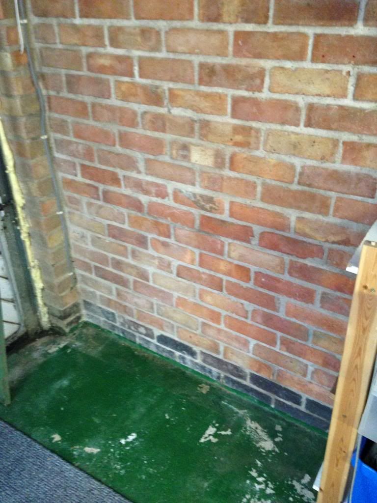 And the new stand 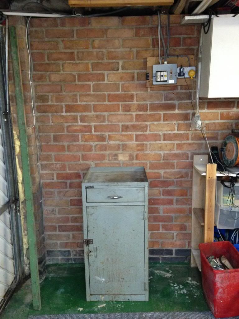 Then I needed to weld in some brackets to hold the mill 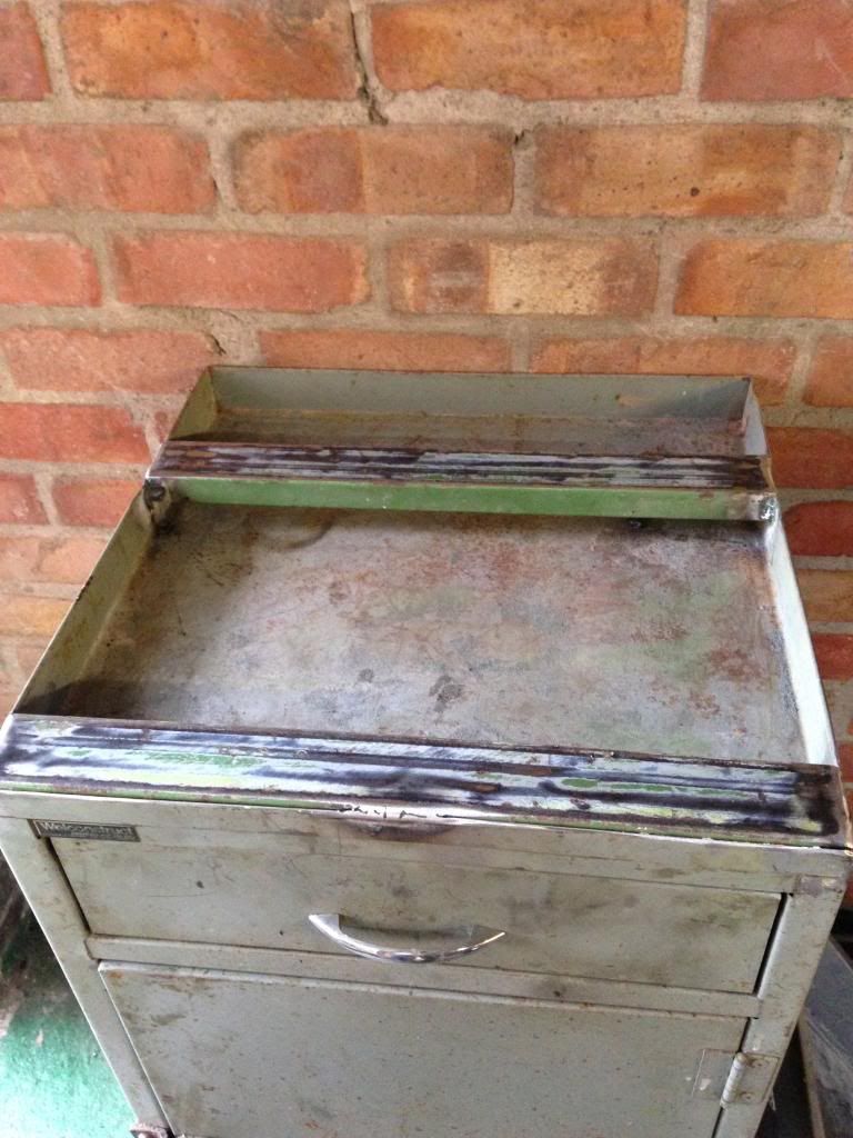 Now it's ready to take the mill and drip tray I am also mounting it on some wood just to spread the load and give the plastic drip tray something to sit on 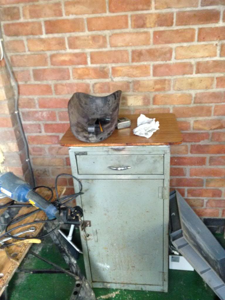 Unfortunately as usual I have ended up with another job in got a nasty shock of the welder my dielectric oil has obviously lost its resistance so I have got to re fill with fresh 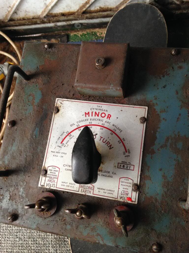 It's a lovely welder very old but one of the best I have ever used any way progress is progress |
|
|
|
Post by Roger on May 24, 2014 11:27:39 GMT
3 phase PWM would get my vote every time given the choice provided you can get the top speed you need. Ok the choice has been made for me the PWM drive is shot so it's back to the brushed dc motor which ironically has the same top speed 4k so I am going to need to find a power supply for about 60 v dc to get the best out of it it is rated at 275w so quite a big step up from the one I have which is only 150w any more would be a waste IMO as the mill is not all that stiff That's a pity, what's wrong with it? Usually these things just blow up the output transistors so it might be worth having a quick look over it to see if those are destroyed. Some of these parts are pretty cheap so it might be fixable. Anyway, the DC motor will be fine, I guess you're off to trawl through ebay then. |
|
|
|
Post by Roger on May 24, 2014 11:31:16 GMT
Wasn't there room in the lounge?
|
|
|
|
Post by Doug on May 24, 2014 11:41:40 GMT
Ok the choice has been made for me the PWM drive is shot so it's back to the brushed dc motor which ironically has the same top speed 4k so I am going to need to find a power supply for about 60 v dc to get the best out of it it is rated at 275w so quite a big step up from the one I have which is only 150w any more would be a waste IMO as the mill is not all that stiff That's a pity, what's wrong with it? Usually these things just blow up the output transistors so it might be worth having a quick look over it to see if those are destroyed. Some of these parts are pretty cheap so it might be fixable. Anyway, the DC motor will be fine, I guess you're off to trawl through ebay then. It's the encoder feedback I think the opto for the return has burnt out its surface mount and un replaceable (can't even see the damn thing) its returning an error hall state error so I checked the encoder and it's fine on other drives never mind. |
|
|
|
Post by Doug on May 24, 2014 11:42:52 GMT
Wasn't there room in the lounge? Don't joke my wife still brings up the motorbike I fixed in the lounge in my first house aaaah the single life! |
|
|
|
Post by Roger on May 24, 2014 11:45:53 GMT
What a pity. Surface mount is a blessing and a curse. I love the space saving but it's a nightmare to work with. I've recently hand soldered a 64pin TQFP device which has legs on a 0.5mm pitch. That's a challenge. A tiny spot of blue tack to hold SMTs in place is a neat trick, especially when some as so small you can hardly pick them up with your fingers.
I much prefer to use the old DIP through hole parts, but some devices can't be bought in those old packages any more.
|
|
pault
Elder Statesman
  
Posts: 1,502
|
Post by pault on May 24, 2014 18:01:40 GMT
Before I met SWMBO I had an Emco compact 5 CNC lathe in my sitting room. It was made very clear that the lathe was not welcome when I moved in with her
|
|


