|
|
Post by Doug on Jun 23, 2014 8:32:09 GMT
my first programs are now made its a good job i ran them through a simulator though the first part i made ran fine rigt up till the last bit where i drill the holes at which point it ran G0 right through the part at 45% whoops just goes to show its always a good idea to test it first. anyway first cut later i hope.
|
|
|
|
Post by Roger on Jun 23, 2014 14:45:53 GMT
Yikes, that was a lucky escape. That's what I like about Alibre CAM, you can view the path in 3D and see it this sort of thing is going to happen. Mind you, the program is unlikely to generate such a move itself, but it has other variation such as cutting the wrong side of the line which would be interesting.
|
|
uuu
Elder Statesman
   your message here...
Posts: 2,860
|
Post by uuu on Jun 23, 2014 18:48:02 GMT
I like to swivel the Mach3 view to have look at what the Z is doing. It shows up if I've made a howler somewhere, or if the CAM program has done something silly.
Wilf
|
|
|
|
Post by Roger on Jun 23, 2014 20:54:54 GMT
I like to swivel the Mach3 view to have look at what the Z is doing. It shows up if I've made a howler somewhere, or if the CAM program has done something silly. Wilf I didn't know you could do that, I'll have to give that a try. I didn't think that view would be terribly helpful on the machine, but it does have its uses. Fist up, you can see if the program looks like the right one. I've loaded the wrong one in the past unwittingly and failed to notice the comment I always have at the top. It's also handy to see where it still has to go, that's another sanity check. |
|
|
|
Post by Doug on Jun 23, 2014 21:37:23 GMT
it has been a good day of machining and I have learned quite a bit I have made one of the three motor mounts it is amazing having CNC I can get so much work done I have a lot to learn with the CAM program though it spent a lot of time doing silly moves and cuts where there was nothing left to cut anyway some photo's of the progress Starting the pocket for the bearing 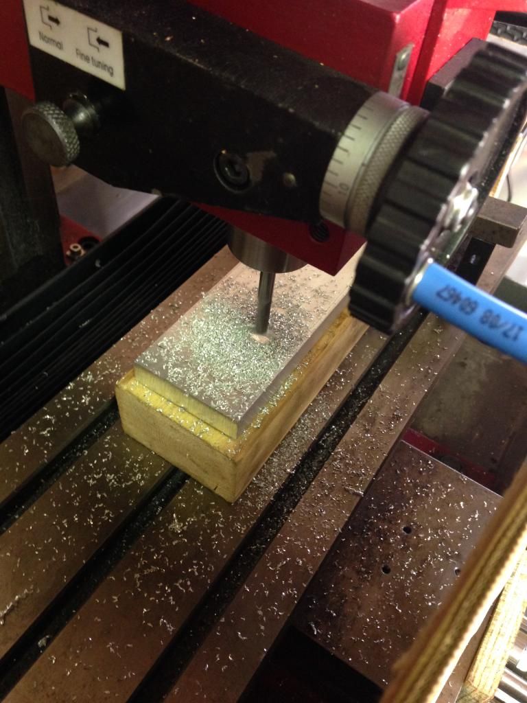 The Y axis bearing block holder completed 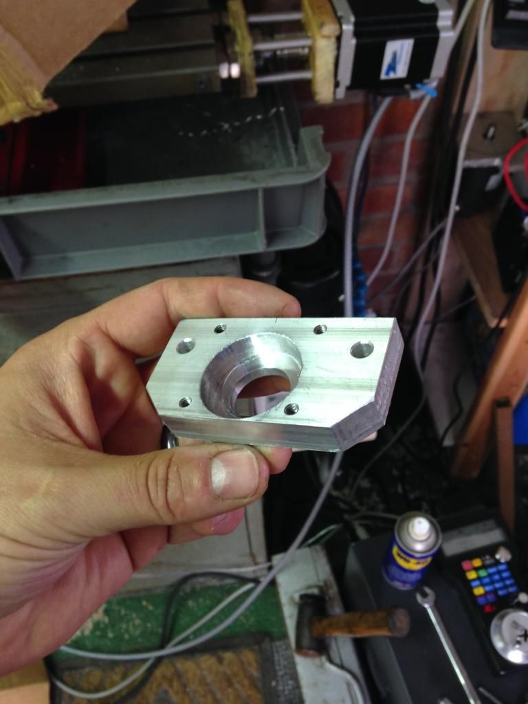 And fitted I just have some spacers to remake and the motor mount plate ( which suffered a bit of damage during a crash but is useable) 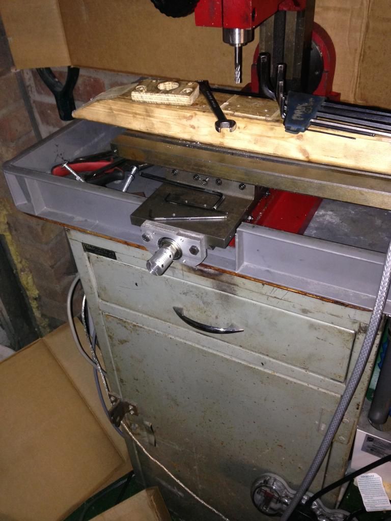 And the motor mount plate just before the Z axis dropped into it 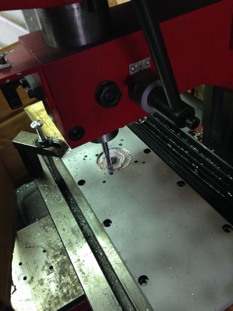 I have a bit more work to do on the Y axis and I can get on and do the X axis next i also now have some ideas regarding some guarding to stop the swarf flying all over the place and I need a small blower to keep the cutter clear it's all good progress. |
|
|
|
Post by Roger on Jun 23, 2014 21:50:52 GMT
Excellent job! Keeping the machine cutting metal and not fresh air is an art you'll get to grips with. Full 3D machining is dreadful for that if you don't really tie down what it's doing. That's why I only use it when it's absolutely necessary.
Most of what I machine is 2D, with one roughing and one finishing cut. You'll quickly figure out the best feeds and speeds for the amount of noise you're prepared to put up with.
What a transformation though, it's a totally different machine once you put a CNC control on it. The sky's the limit now.
You might consider looking out for a thin three jaw chuck that can be bolted down to the table so you can use the 'Part on a stick' method from round bar. I ought to get round to adapting the old 3 jaw chuck that came with the Warco, that would be handy for repeat work.
|
|
|
|
Post by Doug on Jun 24, 2014 9:12:36 GMT
i have ordered a ripper cutter off ebay so i can see what better performace i can get when milling pockets etc i have come up with a nice trick of adding a over size off set polly line to the finish size so that i can take a fine deep cut to trim it up at the end it should improve the finish i am getting too. I like the idea of the parts on a stick and i just happen to have a 5" chuck i dont use as its not very acurate but it wont make any diferance if its just holding a bar  |
|
|
|
Post by ejparrott on Jun 24, 2014 11:48:45 GMT
I usually program a mill path to finished size and let the machine work out the tool offsets from a given tool diameter. If I plan to use a 10mm cutter, I'll put in a 10mm ripper and in the tool library tell it it's 11mm diameter, the machine then stands off and leaves half a mm on for finishing. I then go back in to the tool library, tell it its a 10.5mm tool, and run the program again with no alterations. The machine will now leave a theoretical .5mm still on it, I can check it, adjust the tool offset again to suit which might mean telling it its a 10.2 or a 9.8 cutter, then run again to finish. There's no need to create multiple programs to do the same job, just use the tool offset. It also means if you need to run the job again but you've only got an 8mm cutter and not a 10mm, you can still run it.
|
|
|
|
Post by Roger on Jun 24, 2014 13:48:19 GMT
i have ordered a ripper cutter off ebay so i can see what better performace i can get when milling pockets etc i have come up with a nice trick of adding a over size off set polly line to the finish size so that i can take a fine deep cut to trim it up at the end it should improve the finish i am getting too. I like the idea of the parts on a stick and i just happen to have a 5" chuck i dont use as its not very acurate but it wont make any diferance if its just holding a bar  Don't forget that you can't finish with a Ripper, it will look like a poughed field. Leave about 0.3mm to clean up as a minimum and then swap to an end mill. It's good practice to split the two operations in my opinion because the roughing cutter takes a lot more of a beating than the finishing cutter. Swapping to a less used one for finishing will probably give you a better finish. I also rough out the whole job if I can before finishing anything in case the machine has to be reset. I try to do all the finishing in one session or leave the machine powered up until it's done. Turning things on and off without a proper referencing system is likely to lose accuracy. I usually break down all of the machining operations into individual cuts. By that I mean, rough out a pocket first. Then finish the pocket with profiling. I don't use the CAM to produce all of the machining operations automatically because it spends most of its time cutting fresh air. That's fortunate having the chuck, it sounds ideal. As you say, the accuracy isn't important, it's just a 3 jaw vice. |
|
|
|
Post by Doug on Jun 24, 2014 15:00:10 GMT
i have ordered a ripper cutter off ebay so i can see what better performace i can get when milling pockets etc i have come up with a nice trick of adding a over size off set polly line to the finish size so that i can take a fine deep cut to trim it up at the end it should improve the finish i am getting too. I like the idea of the parts on a stick and i just happen to have a 5" chuck i dont use as its not very acurate but it wont make any diferance if its just holding a bar  Don't forget that you can't finish with a Ripper, it will look like a poughed field. Leave about 0.3mm to clean up as a minimum and then swap to an end mill. It's good practice to split the two operations in my opinion because the roughing cutter takes a lot more of a beating than the finishing cutter. Swapping to a less used one for finishing will probably give you a better finish. I also rough out the whole job if I can before finishing anything in case the machine has to be reset. I try to do all the finishing in one session or leave the machine powered up until it's done. Turning things on and off without a proper referencing system is likely to lose accuracy. I usually break down all of the machining operations into individual cuts. By that I mean, rough out a pocket first. Then finish the pocket with profiling. I don't use the CAM to produce all of the machining operations automatically because it spends most of its time cutting fresh air. That's fortunate having the chuck, it sounds ideal. As you say, the accuracy isn't important, it's just a 3 jaw vice. do you have a system to produce your programs then i was going to write mine manually initally until i tried it and its so complex it can take 1000 lines just on a simple profile i can see how individual programs would be beneficial, i used M01 to good effect though yesterday on my drilling opps i moved to the correct position, optional stopped it and drilled the hole with the quill feed manually, then swapped the drill size as required and pressed cycle start tot move to the next hole etc. made the process very easy indeed. i like the idea of having the programs seporate though producing a suite of programs for a part makes alot of sence esp. if you use ED's idea of offset tooling, makes mulitple runs of the same opp quite easy. all this makes me wonder why i didnt do it earlier!!! I have a really good idea for the Xaxis bearing leadscrew assembly but its going to take some serious work to get it cut up first (manual hacksaw) and i need to finish off the y axis motor mount as well its going to be reallt good when its finally finished but its great fun learning how to use CNC while building itself. i really want to get on and do some more machining tonight but i am off to donnington park racetrack on my bicycle tonight £1 entry (rude not to really) got to beat my 12 min lap time!!! |
|
|
|
Post by Roger on Jun 24, 2014 15:28:39 GMT
You can certainly write the simple things manually, just be careful when you do a dummy run. I've done it on other machines in the PCB industry and for Heidenhain machines but it's a bit painful. I don't know what cheap CAD/CAM options there are out there, mine's pretty dear. I'm sure there are some free ones that will take a lot of the work out of it. Alibre CAD and the CAM package that integrates with its are very powerful though and the money I get from using it commercially justifies the expense. I don't think I could do that if it was just for this.
I very rarely use a drilling cycle unless there are dozens of holes. I just output them as a series of positions and single step between them. You'll find that it's much quicker to leave the centre drill in the chuck and step between each hole and then swap the tool and come back to do the next op. It's counter intuitive because usually you go to great pains to make sure you're at the right spot and then do all the operations on that hole. There are lots of things like that which take a while to sink in. It sounds like you're learning fast though.
I wrote a utility program that all my outputs go through. My CAM system generates .cnc files and my utility converts them to .nc files. Most of the time I don't make any changes but I can do all sorts of conversions that I've needed in the past. One of those allows a comment of the style (XSTEP5X70.0YSTEP3Y50)to create a series of repeated images at G92XY offsets. I could use that on the machine but I prefer to then merge the offset with the program so that I end up with a panel of stepped images that are absolute. For me, absolute is best. There's no doubt about which offset you're using or what's going to happen if you try to restart part way through. It's a bit messy as a program but you're welcome to a copy if you want to play.
Good luck on the track, pedal extra hard this time.
|
|
|
|
Post by Doug on Jun 25, 2014 7:05:44 GMT
You can certainly write the simple things manually, just be careful when you do a dummy run. I've done it on other machines in the PCB industry and for Heidenhain machines but it's a bit painful. I don't know what cheap CAD/CAM options there are out there, mine's pretty dear. I'm sure there are some free ones that will take a lot of the work out of it. Alibre CAD and the CAM package that integrates with its are very powerful though and the money I get from using it commercially justifies the expense. I don't think I could do that if it was just for this. I very rarely use a drilling cycle unless there are dozens of holes. I just output them as a series of positions and single step between them. You'll find that it's much quicker to leave the centre drill in the chuck and step between each hole and then swap the tool and come back to do the next op. It's counter intuitive because usually you go to great pains to make sure you're at the right spot and then do all the operations on that hole. There are lots of things like that which take a while to sink in. It sounds like you're learning fast though. I wrote a utility program that all my outputs go through. My CAM system generates .cnc files and my utility converts them to .nc files. Most of the time I don't make any changes but I can do all sorts of conversions that I've needed in the past. One of those allows a comment of the style (XSTEP5X70.0YSTEP3Y50)to create a series of repeated images at G92XY offsets. I could use that on the machine but I prefer to then merge the offset with the program so that I end up with a panel of stepped images that are absolute. For me, absolute is best. There's no doubt about which offset you're using or what's going to happen if you try to restart part way through. It's a bit messy as a program but you're welcome to a copy if you want to play. Good luck on the track, pedal extra hard this time. hi roger i am using CAMBAM at the moment which is quite good and to get better i would prob. need to spend alot of money we use DelCam at work but the licence's are thousands i can get pretty much all the jobs i will need done with CAM BAM i have not even looked at the 3d profiling yet thats quite a long way off, i am myself not a great fan of using offsets they are only really handy when using a tool changer or if you have a secound milling head/router fitted i dont want to use the G92 unless i have to. I will continue on the building of the machine till i have that completed and move on to some simple jobs i have lined up for Speedy . I now have all the parts i need for the Z axis ball screw which is really good as the lead screw i have currently is not long enough so the cutter cant reach the table top. I have no idea why so many people have counter balenced the z axis on the Sieg x1l as the motor is more than powerfull enough to drive it up and down and the counterbalence system gets quite messy round the back of the machine. I have currrent limited the motors to 75% rating once the ballscrew is fitted the motor loading will come down even more. |
|
|
|
Post by Roger on Jun 25, 2014 11:56:12 GMT
I've not heard of that one, I'll have to drop by when I'm up your way and have a look. I think Alibre is somewhere in between the ultra low cost end and the likes of Solidworks and Delcam. It might be worth looking at it later if you need something more powerful. The main thing is that you can clearly automate the G-Code production so that's the main thing.
I don't know what options your CAM gives you for entry moves, but I've experimented with all sorts of strategies and when I need to enter the surface of the work, I've found that a 10 degree slope is a bit too much for a really smooth entry, I've settled on 5 degrees. That seems to work for pretty much any size of cutter and gives you the opportunity to get the feel for how it's going as the depth increases. You can tweak the feed and speed as it bites if you're taking a deep cut.
I agree that counterbalancing is not necessary. My knee isn't counterbalanced and that's one heavy item with the X and Y carriages on top. I used a DC braked version of the SureServo because with the power off, it wants to gently settle down to the bottom. The advantage of not counterbalancing the Z-axis means that you don't have big issues with backlash. I wouldn't want to completely balance it for that reason alone. People talk a lot of rubbish about CNC when they haven't tried things themselves. I don't take anyone's word for anything because it's human instinct to dress up opinion and predjudice as fact. If I'd listened to all the 'experts' and 'experienced' builders, I'd have settled for 10-20micron resolution, purely because that's what they had and it seemed ok. That would have thrown away accuracy unnecessarily. I think you're right to follow your own mechanical instincts, you won't be far wrong and you can backtrack on the things you aren't 100% happy with.
|
|
|
|
Post by Doug on Jun 25, 2014 21:22:27 GMT
I have had another good afternoon machining and fixing I have got the y axis motor mount completed 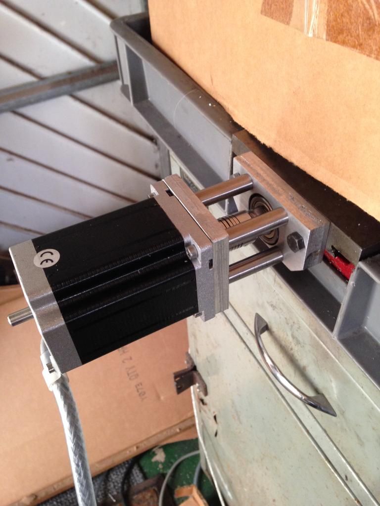 I then started to make the x axis motor mounting plate (re run of the y axis program) and had a throw at what I need regarding swarf guarding 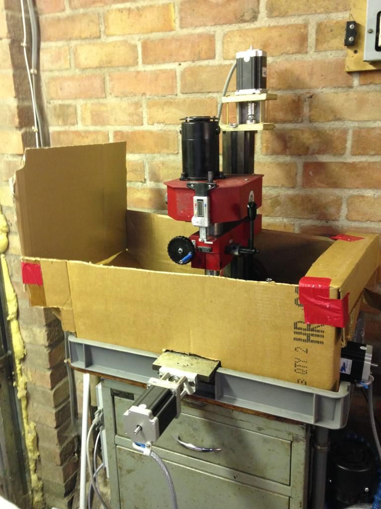 The guarding should look a bit like this however it still came over the top so I thought about a re-moveable panel 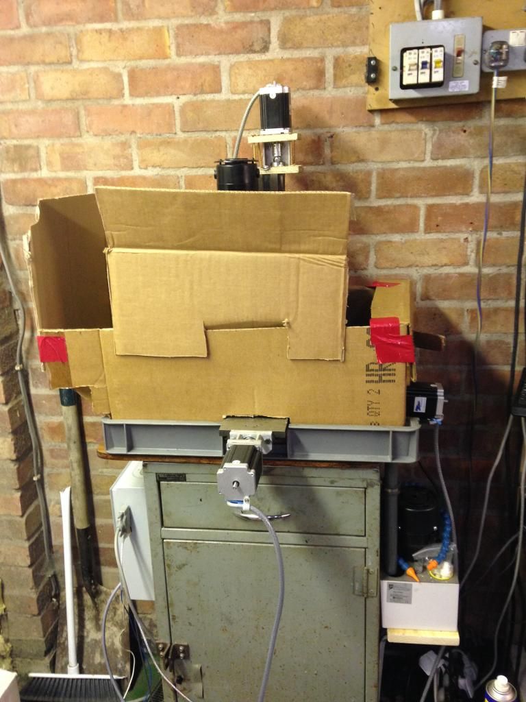 I will have to refine the design as I try out my various vices and rotory tables. anyway got the x axis plate cut 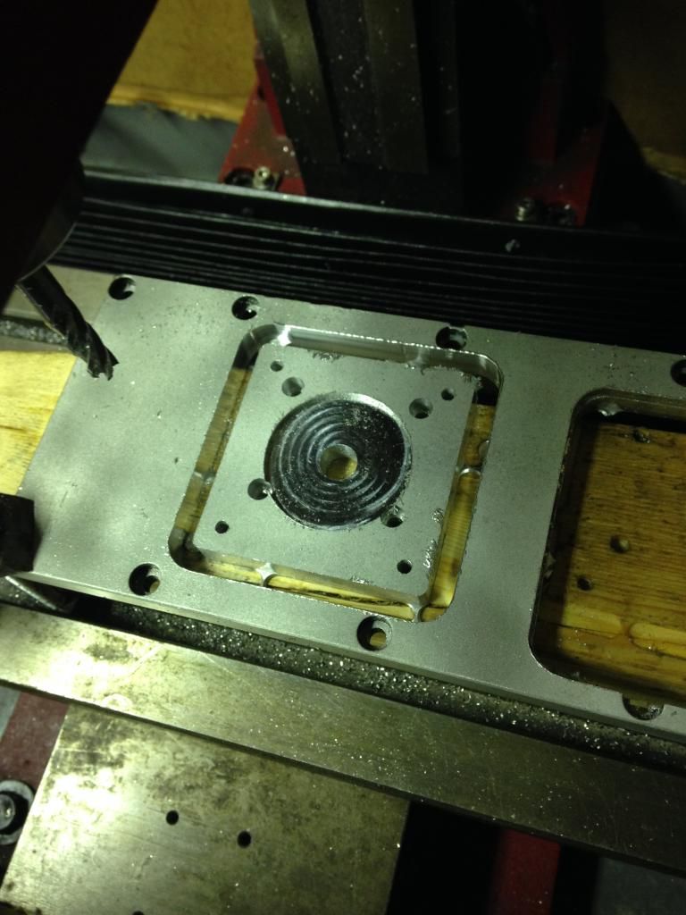 I have to redo the G-code for the x axis bearing mount as I want to use my new ripper and split the program into opp's also making slots (profiling) needs to be wider than the cutter so I need a bigger kerf width to clear the swarf. |
|
|
|
Post by Roger on Jun 25, 2014 22:31:21 GMT
You certainly have been busy. I wonder how long that would have taken on the old mill, pre CNC?
|
|
|
|
Post by Doug on Jun 26, 2014 7:24:43 GMT
You certainly have been busy. I wonder how long that would have taken on the old mill, pre CNC? It took two hours of machining to make the motor plate and i could not have done the same opp before as the radius are done by interpolation (not a skill i have mastered by hand LOL) joking aside i could not have practically done that job on this mill i would have had to use the one at work so i can take "proppercuts" the biggest thing i am enjoying so far is like the motor plates re running a program, press go walk away. for my next screw mounting plate (x axis) i have split the programs and made a roughing out part program with extra clearances for swarf its a 30mm deep plate so should be a challenge for the little mill looking forward to giving it a really good test. i am going to cut 25mm deep and chop the reamining material by hacksaw and clean up afterwards not the best but i am a little tied until i get the z axis sorted so i can reach the table. so far anyone reading this and wondering if you should take the CNC plunge DO IT! its awsome! (although you have to learn alot of new skills) tool paths for the new plate; 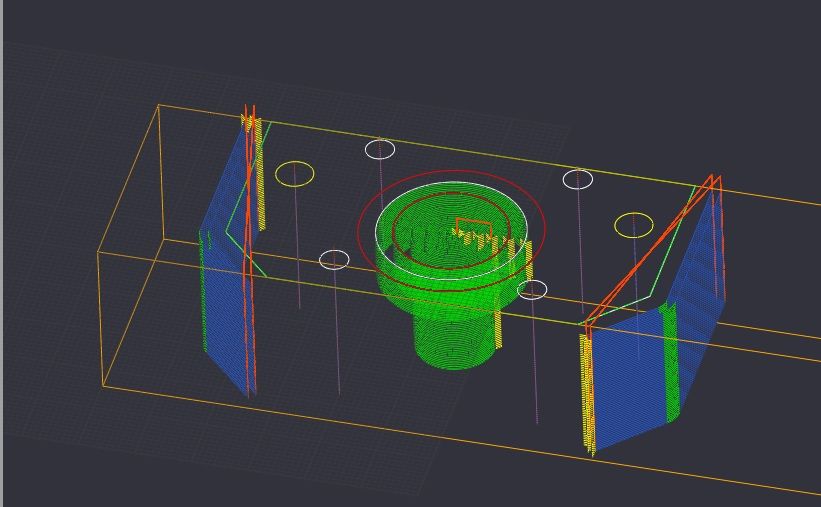 |
|
|
|
Post by Roger on Jun 26, 2014 9:41:34 GMT
I don't think two hours for that plate is too bad, you'll find quicker ways that suit the rigidity of your machine as you gain more experience. You certainly have an awful lot of cuts, that's a very different approach to mine and much more in keeping with what you see on Youtube. I'm not convinced that you actually remove the material any quicker that way and it gives one tiny portion of the tool a very hard time while the rest does nothing. It's worth experimenting with halving the feedrate and doubling the cut depth as an experiment. You could keep doing that until the machine complains and then you'll know the whole range of ways to go about it. Just be sure to lower the spindle speed too. Obviously my spindle is a lot more rugged than yours which is both good and bad. That's why I've added a high speed spindle on the side.
You might consider drilling out a big hole in the middle of the pocket and adjusting the program to suit. It might save a lot of time.
It looks like the tool plunges straight into the work. Are there any controls for entering the work along the 2D path? I'd certainly use that if you can, it's much less brutal on the cutter and the spindle.
Anyway, I'm pleased you are obviously delighted with what you've done to your machine, I think it's great.
|
|
|
|
Post by Doug on Jun 26, 2014 10:04:04 GMT
I don't think two hours for that plate is too bad, you'll find quicker ways that suit the rigidity of your machine as you gain more experience. You certainly have an awful lot of cuts, that's a very different approach to mine and much more in keeping with what you see on Youtube. I'm not convinced that you actually remove the material any quicker that way and it gives one tiny portion of the tool a very hard time while the rest does nothing. It's worth experimenting with halving the feedrate and doubling the cut depth as an experiment. You could keep doing that until the machine complains and then you'll know the whole range of ways to go about it. Just be sure to lower the spindle speed too. Obviously my spindle is a lot more rugged than yours which is both good and bad. That's why I've added a high speed spindle on the side. You might consider drilling out a big hole in the middle of the pocket and adjusting the program to suit. It might save a lot of time. It looks like the tool plunges straight into the work. Are there any controls for entering the work along the 2D path? I'd certainly use that if you can, it's much less brutal on the cutter and the spindle. Anyway, I'm pleased you are obviously delighted with what you've done to your machine, I think it's great. the cut depths are only 0.4mm which iswhy there are so many tool paths i am going to try and experiment with deeper cuts but for now i am stuck with light cuts as i cant get to the table because of my reduced z axis stroke and fixturing at height is not a good idea with heavy cuts. the tool entry angles are adjustable currently the tool just plunges in to the work not something i am too bothered about at the moment as i am cutting aluminium and very shallow cuts. however i have found the advanced tab on CAMBAM and it has all the extra stuff i will use later on once i have learned how to implement the various commands, like aproach vectors and cutoff distances it does not look too far off from what i already understand about machining so shouldnt take too long to learn. All the holes/ pockets can be machined with tangental aproach'es which i find can give better results both in roundness and edge quality, the default is a vector cut which is a bit rough. I am likeing the look of the CAM software its very easy to use (initally looked too simple) and once you go looking it has all the functionality you could ever want and a bit more besides. So before i get buried in to it i want to do the "simple brackets and plates" for the machine once i am used to the methodology i will start to expand on the techniques (i am watching very closely indeed to what yourself and others are doing with the CNC's to pickup techniqes) i am only on my third part and already i am using massively different methods to make the parts. Happy days!!  |
|
|
|
Post by Roger on Jun 26, 2014 10:27:08 GMT
Happy days indeed, and you're learning so fast. I'm impressed with what you're able to do with the CAMBAM for so little outlay. I'm not sure that the deeper and slower cutting method adds much force to the job if you get the balance right. After all, you're removing the material at a similar rate until you get braver with the feedrates.
Anyway, you're approach of learning on the job is a great way forward and you'll learn far more than anyone can tell you. Your system is different to anyone else's so don't take too much notice of what others do, it may not work for you.
Plunging in to 0.4mm depth isn't an issue, but much deeper and it will be. The cutter will make a nasty oversize entry and you won't like the sound of it either. Try 5 degrees when you play with it and you'll see what I mean.
Another trick that's worth using is this. Rough to a known offset ie leave say 0.3mm on the job. Then plunge into that with a 0.3mm lead in for the finishing cut. That way you can do jobs where you can't easily remove the material from the outside before finishing.
|
|
|
|
Post by Doug on Jun 26, 2014 22:15:09 GMT
We'll that was a bit laborious took 4hours of machining to rough out I need to get a handle on my cut depths I had a couple of light mishaps when I decided to retune the motors old max feed rate 113mm/m new feed rate is now 223mm/m which is now fine any more and the motors stall, I am rewriting the finishing program tomorow to increase the cut depths and use ramp angle approaches. I now have some machining marks in my part to remember my learning curve by. The new ripper cutter does what it says on the box 3mm cut noooo problem sir. So another session another few lessons learned and another big step closer to getting the machine finished. Overall pretty happy with the performance but I can't wait to get the new spindle fitted the old one is just noisy and annoying. The power supply is a bit of a problem as it needs 350w so I am looking into my options.
|
|