|
|
Post by Roger on Jun 27, 2014 5:43:52 GMT
Huge progress again then, and no real harm done. All new processes are going to cause problems like that. I'm struggling with getting the ends of the flutes good enough, and that's going to massively impact on the run time.
I'm pleased you like the Ripper, I think they're brilliant and they seem to just go on and on. I think it's because each tooth shares the work and is required to take a bigger bite because it's not following directly in the wake of another one. Whatever the reason, they seem to make light work of it.
|
|
|
|
Post by Doug on Jun 27, 2014 7:34:53 GMT
Huge progress again then, and no real harm done. All new processes are going to cause problems like that. I'm struggling with getting the ends of the flutes good enough, and that's going to massively impact on the run time. I'm pleased you like the Ripper, I think they're brilliant and they seem to just go on and on. I think it's because each tooth shares the work and is required to take a bigger bite because it's not following directly in the wake of another one. Whatever the reason, they seem to make light work of it. progress indeed i have re done the G code for the cuts it now looks like this; 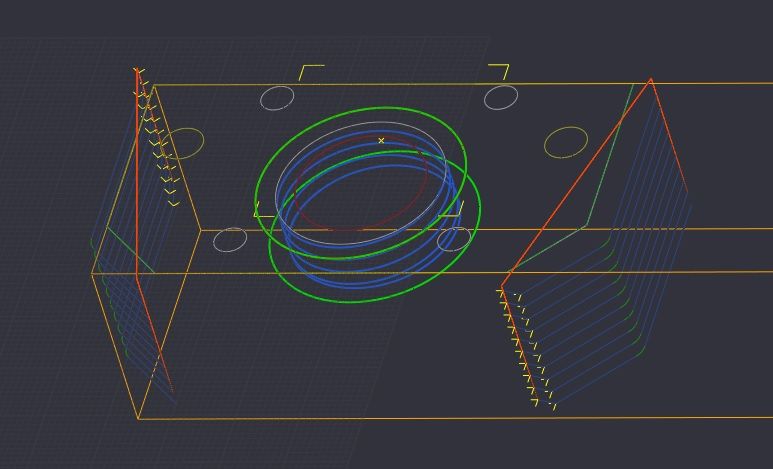 much better and now with lead in so less stress on the cutter regarding the flutes why not use a tee slot cutter that is the usual way and it makes the radius by ending the cut it will save all that 3d profiling and cleaning up after? |
|
|
|
Post by Roger on Jun 27, 2014 8:06:17 GMT
That looks more like it, I'll be interested to hear how that works out.
I certainly won't rule out using a tee slot cutter but the flute is narrower at one end compared to the other so a change of setup would be required. The cutter would also foul the bolts holding it in place so it's not quite as simple as that. To do it that way, it would be better to have added the flutes when the side scollups were done really. I need to get to grips with the 3D machining anyway, so this is a good opportunity to do that. I've got four sides to have a go at, this one can get tidied up by hand and be on the back if it's not quite as good as I'd like.
|
|
|
|
Post by Doug on Jun 27, 2014 8:58:55 GMT
That looks more like it, I'll be interested to hear how that works out. I certainly won't rule out using a tee slot cutter but the flute is narrower at one end compared to the other so a change of setup would be required. The cutter would also foul the bolts holding it in place so it's not quite as simple as that. To do it that way, it would be better to have added the flutes when the side scollups were done really. I need to get to grips with the 3D machining anyway, so this is a good opportunity to do that. I've got four sides to have a go at, this one can get tidied up by hand and be on the back if it's not quite as good as I'd like. my Great-grandad used to machine them with tee slot cutters; mount the rod side on, one fixed hole (small end) and a slot on the fixture large end that way you machine one run down to take the first cut then slide the big end up the slot re-tighten and cut again giving the wide cut one end. It is fairly conventional to do it this way i have seen a few setups including full size and a horizontal mill its the rod that gets moved not the cutter. you can use CSK screws to reduce the head height to clear the cutter. |
|
|
|
Post by Roger on Jun 27, 2014 16:14:59 GMT
Ah, ok I see now. I've been playing with the 3D contouring and reckon I've cracked the main issue I was having. I couldn't figure out a way to define just the level from which the contouring needed to start from. Along the way, I've made a slight cockup which has left a witness on the runout from the slot which is annoying, and I can see that I shouldn't have gone quite so deep by about 0.5mm. Still, it's not a bad effort and I'll think about whether to just put that one on the inside where it's not on view.
I'll give the full new treatment to the other side of that first one and then if I'm still not happy, at least I'll know what to do for the final one. The result is pretty good and it makes a change to see my machine zipping up and down on the finishing cuts up to 1M/min It doesn't take too long at that rate, so I might go for an even finer finish just to see if it makes much difference.
Although it does take a bit of time, it's a cracking way to do it because there is only one setup and you can have tapered sides and any root radius you like for the sake of drawing it. The cutting forces are also tiny so the setup doesn't have to be that sturdy even though it is. Looking at 1501, I reckon there's a sizeable radius at the root of the 'I' section and it looks like it has tapered sides too. I wouldn't place a bet on that though.
|
|
|
|
Post by Doug on Jun 27, 2014 21:54:13 GMT
I have made a start on the guarding I am going to make a metal tray around the base on which I can sit various shields depending on the job in hand and fixtures etc. so the front is done,  The back will be next after I have fitted the z axis ballscrew then I will fill in the sides the x axis bearing block this was much quicker now I am getting used to the CAM software so it just cuts the metal not air 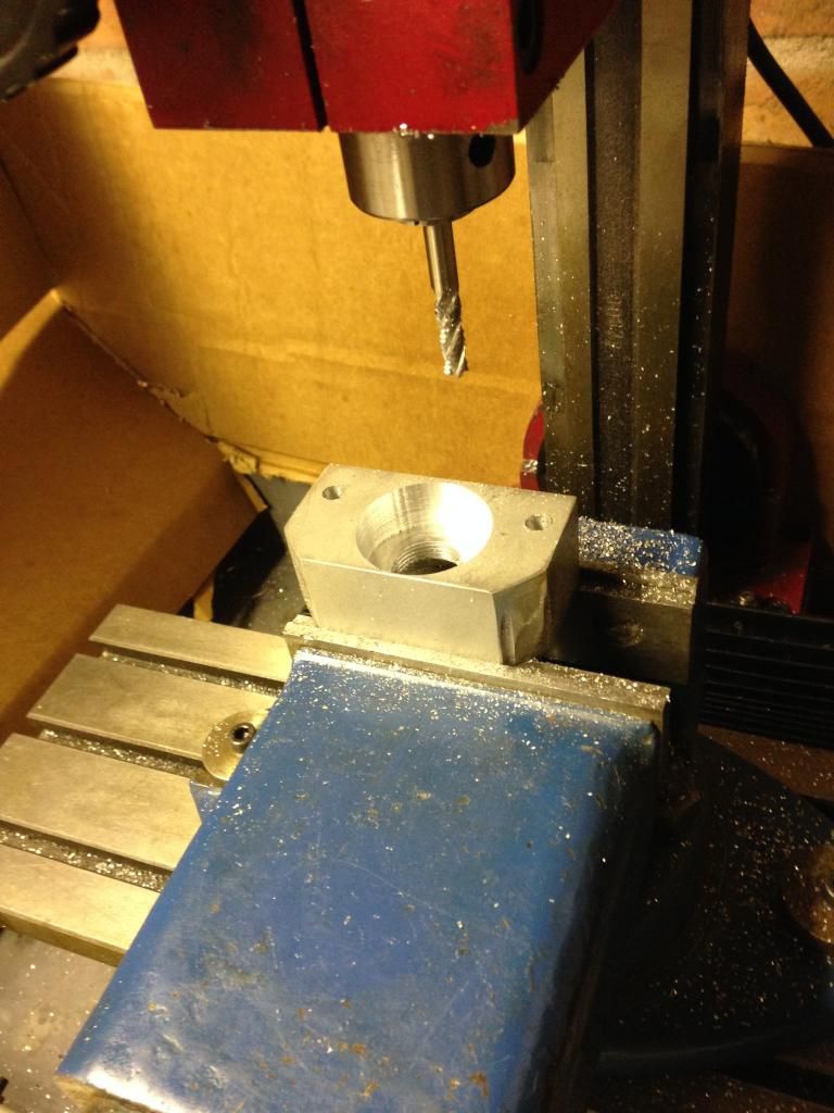 And the same bit fitted and the x axis is done just the z axis to go next 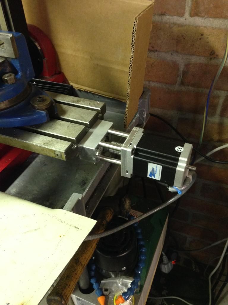 It is certainly coming along nicely not too much longer and I should be able to start doing train parts on it  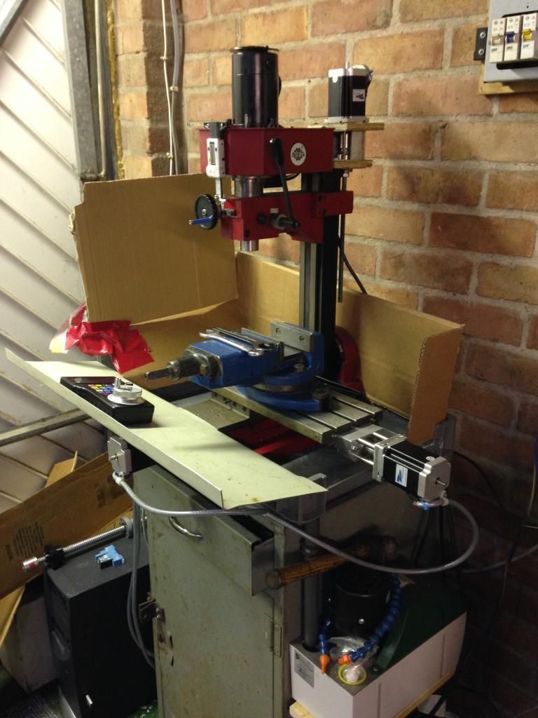 That's all from me for a bit I have got to have a serious think how I am going to do the z axis the ballscrew is in the back of the pic on top of the pc on the left. |
|
|
|
Post by Roger on Jun 27, 2014 22:37:19 GMT
Nice one, and that looks like a manly kind of leadscrew you have for the Z-axis.
I really ought to think about splash guards for mine, I've only got a piece that hooks on the front, and I can't always fit that. A flexible system like yours is probably best. I did think of using hanging plastic strips like they have for warehouse doors, the kind that Fork Trucks can drive through. I think some kind of larger catch tray at the bottom might be a good place to start.
|
|
|
|
Post by Doug on Jun 29, 2014 20:35:00 GMT
Ok still busy building and refining the machine while I sue the mill to make the final bits for the z axis ballscrew I decided to work on the guarding a bit  The z axis is a lot more complex to design and machine but I am getting the hang if the programming now I am splitting the program into operations and making the cam program work hard for me. It's not too difficult just need to think ahead and imagine what it's going to need to do. the new guarding may end up as a box still working it out as I go 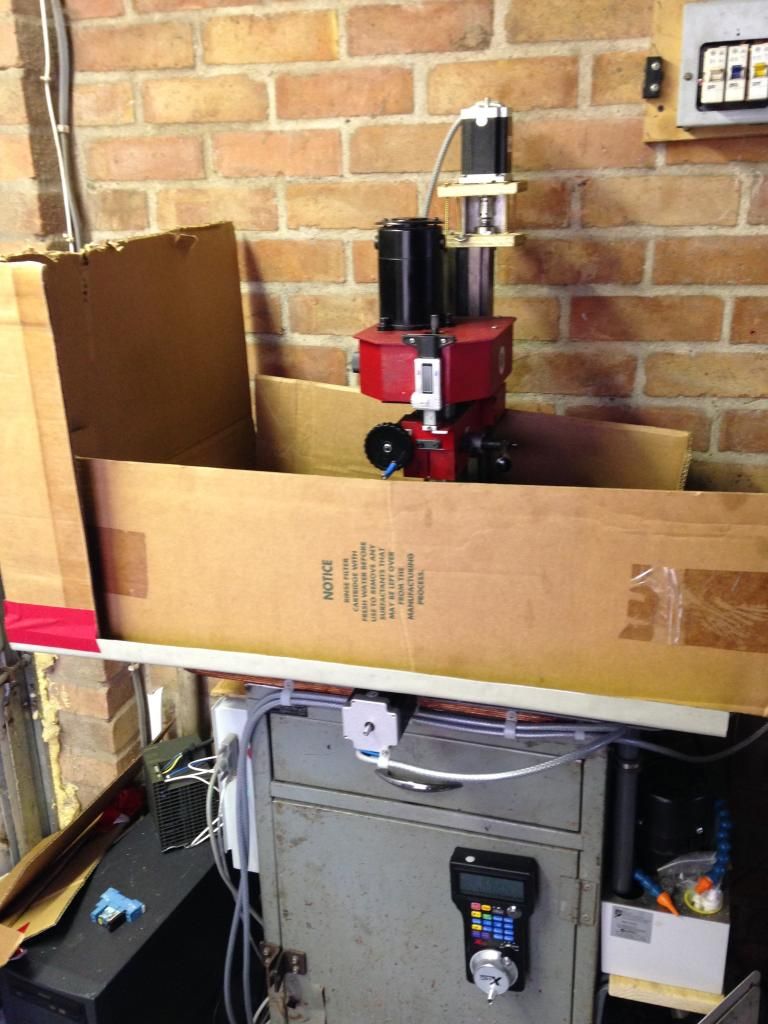 |
|
|
|
Post by Roger on Jun 29, 2014 20:56:45 GMT
If you can afford the space then nice big catch trays like that are ideal. Sadly I'm so wedged in I can't do that.
As you say, the machining is all about figuring out each set of cuts. I imagined the software would do most of that stuff for me, but as you've found, it's great at cutting 90% fresh air and 10% metal so it's pretty much useless for that. I don't know how your CAM program works, but Alibre lets you define groups of machining operations. You can output any of them on their own, but you can output the whole group. That's handy when you've got several operations with the same tool size. You can prove each section and then output the whole lot in one big file when you're happy.
|
|
|
|
Post by Doug on Jun 29, 2014 22:17:50 GMT
No sadly it's not that good I just made the ballscrew mounting plate with three program's made up go op01 drilling the pockets (4off) then op02 drilling operation 12 holes two sizes ran this one twice once to spot all the holes with a center drill and again to drill the holes then finally opp03 profile cut to define the outer shape all in it took 5 hours of machining and two hours to measure, design, draw up and CAM the drawing. However if I had to do it by hand it would have taken about a month my machine is not really capable of making such big parts but with the CNC I can take my time. I have quite a lot of fitting to do next before I can move on to the next bit, I will be glad when all this is done and I have a finished machine and I can get back to my steam engine. I will post some photo's of the z axis ballscrew mounting plate tomorow, I still have one, maybe two more big assembly's to go before I am done.
|
|
|
|
Post by Roger on Jun 29, 2014 22:44:59 GMT
To be honest, I only merge programs together very occasionally because it's usually only one or two off that I'm making. You can always cut and paste them in Notepad if you need to do the same.
It won't be long before you really start to reap the rewards of your efforts in the form of much more rapid progress on the locomotive. It's not only going to speed things up, but you'll find it's that much easier to make things accurately. Jobs that were tricky like expansion links and die blocks will be a piece of cake. The same goes for any valve linkages you may still need to make. Happy times ahead methinks.
|
|
|
|
Post by Doug on Jun 30, 2014 9:53:14 GMT
as I promised last night the z axis ballscrew mounting plate 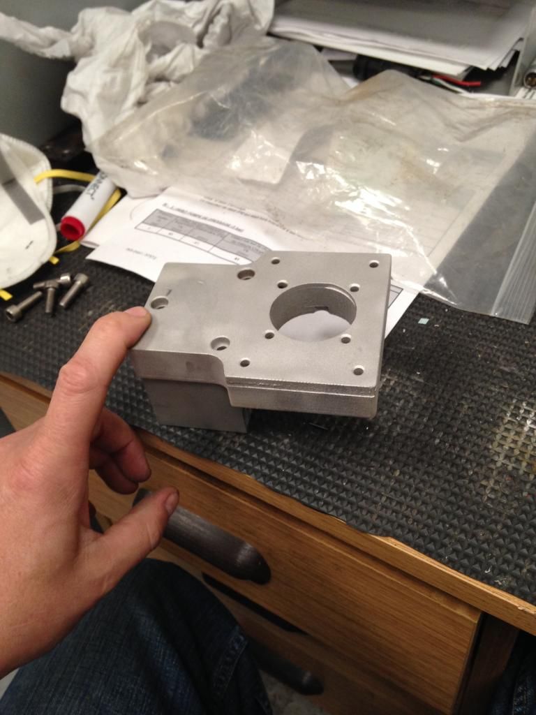 thats a 20mm thick plate almost certainly overkill but the mill is bendy enough so i dont want my additions making it any worse. |
|
|
|
Post by Roger on Jun 30, 2014 16:36:23 GMT
I agree, make it all as strongly as you can, everything bends to some degree so the more metal the better.
|
|
|
|
Post by Doug on Jun 30, 2014 17:50:44 GMT
Ooh I don't half love the CNC stuff I had a trial fit of the ballscrew assembly and ....... It all fitted first go no issues at all I confess myself shocked 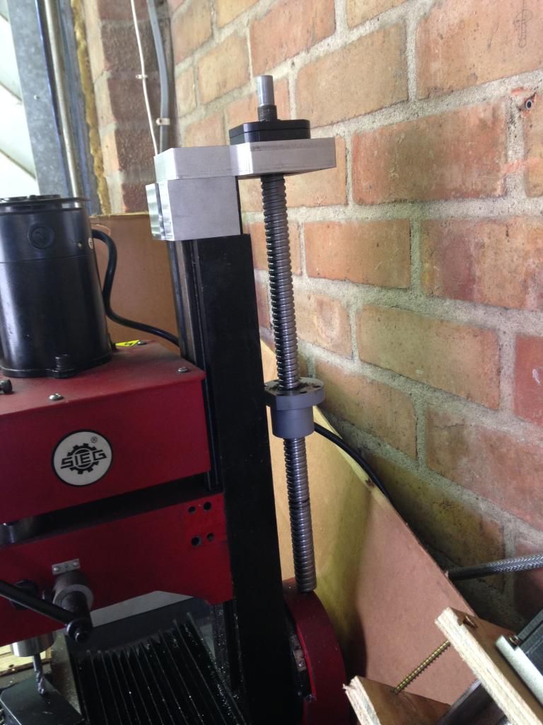 |
|
|
|
Post by Roger on Jun 30, 2014 18:49:04 GMT
Get used to it, that happens by default for things like fixing holes. You won't ever have to think about spotting things through again, just do it all to the drawing on the CNC.
So what size is that leadscrew, it looks pretty manly? Mine are all 25mm which makes for a pretty rigid setup. That looks like 5mm pitch like mine too. With stepper motors, you ought to find that it doesn't fall under it's own weight.
So not that far to go now then.
|
|
|
|
Post by Doug on Jun 30, 2014 19:26:36 GMT
Get used to it, that happens by default for things like fixing holes. You won't ever have to think about spotting things through again, just do it all to the drawing on the CNC. So what size is that leadscrew, it looks pretty manly? Mine are all 25mm which makes for a pretty rigid setup. That looks like 5mm pitch like mine too. With stepper motors, you ought to find that it doesn't fall under it's own weight. So not that far to go now then. The screw is 18mm and 5mm pitch it is a bit oversize but oddly cheaper than the next size down, I have three bits to make the motor plate (need to order some 10mm stock plate for this) a ball nut mounting which I will use some more 20mm plate for and a arm to go between the ball nut mounting and the head which I might make from steel (just because I have some the right size) i am getting some fearse chatter from the head so it's going to get a good look at it might be a bit loose on the jib (I replaced the old one with a brass one a few weeks ago) and the spindle is very very noisy so I have ordered a belt and some gears. I also need to replace the spindle motor when I have built a suitable power supply (it then needs to be intergrated into mach 3) so quite a bit left really. i have also been looking at my cutters I have a nice collection of solid carbide mills but I need to order an 8mm collet as I have 3 8mm carbide (2off ball nose 1off end mill) cutters and no way of holding them I still have quite a few 6mm and 10mm ones though. then there's the coolant I am thinking I would like mist, the flood coolant needs loads of work and a tank to put the sump pump in, I have a weir tank mounted on the side of the machine (to catch swarf) so it's about half done. |
|
|
|
Post by Roger on Jul 1, 2014 6:50:52 GMT
Have you tried Aluminium Droitwich for Aluminium? They're on ebay and I buy most of my stock from them. I can get it cheaper delivered than I can picking it up from my local stockholder.
When you say you replaced the old big strip, I'm guessing that it's not a tapered type then. What was the old one made of? I'm not sure Brass is a good choice, maybe a little research might come up with a better one?
I'm still living with coolant being aplied by hand, and it's not enough of a nuisance to go to the effort of changing that. I've got most of what I need to do the job, but the mess it's likely to make in practice puts me off doing it. I can't be doing with a compressor running all the time either, even though mine's a hydrovane and I'm running it slowly through a VFD.
|
|
|
|
Post by Doug on Jul 1, 2014 7:16:48 GMT
Have you tried Aluminium Droitwich for Aluminium? They're on ebay and I buy most of my stock from them. I can get it cheaper delivered than I can picking it up from my local stockholder. When you say you replaced the old big strip, I'm guessing that it's not a tapered type then. What was the old one made of? I'm not sure Brass is a good choice, maybe a little research might come up with a better one? I'm still living with coolant being aplied by hand, and it's not enough of a nuisance to go to the effort of changing that. I've got most of what I need to do the job, but the mess it's likely to make in practice puts me off doing it. I can't be doing with a compressor running all the time either, even though mine's a hydrovane and I'm running it slowly through a VFD. i got a very cheap off cut from ebay it was £6 and plenty big enough for my motor plate  the old gib strips are made of steel i replaced the x axis one a couple of years ago to great effect what useually happens is it beds in and once re adjusted its pretty good and reduces the friction quite a bit PTFE backed steel would be my first choice but the gap is too small to have a composite gib so brass is the next best alternative. TBH i hate the gib strips they always fit corse threads so the adjustment is not very good and when you tighten the darrn things up with the locking nuts it pulls the grub away and messes up the adjustment its a right load of cR@p. I intend to fit small rails in the future so i can reduce the lateral play and friction this may also give me some height to fit ballscrews in but for now it will suffice. |
|
|
|
Post by Roger on Jul 1, 2014 14:27:11 GMT
Fair enough, I'd hate you to spend more than you need. I know what you mean about gib strips, they're hard enough to set right however well they're made without making it even more difficult.
Small rails would be great, and you'd probably get a lot less backlash. I'm not sure how rigid they are though, so quite how they would affect things like chattering I don't know. It would be interesting to ask the question on the Forum in case someone can shed any light on it.
|
|
|
|
Post by Doug on Jul 2, 2014 19:51:07 GMT
Still making progress the guarding is coming along nicely but I can't progress much more without finishing off the z axis ballscrew (I can then fit the rear guards) the front screen will have two handles on and will lift off.  The z axis ball nut mounting plate has been finished so down to the last two parts to make now 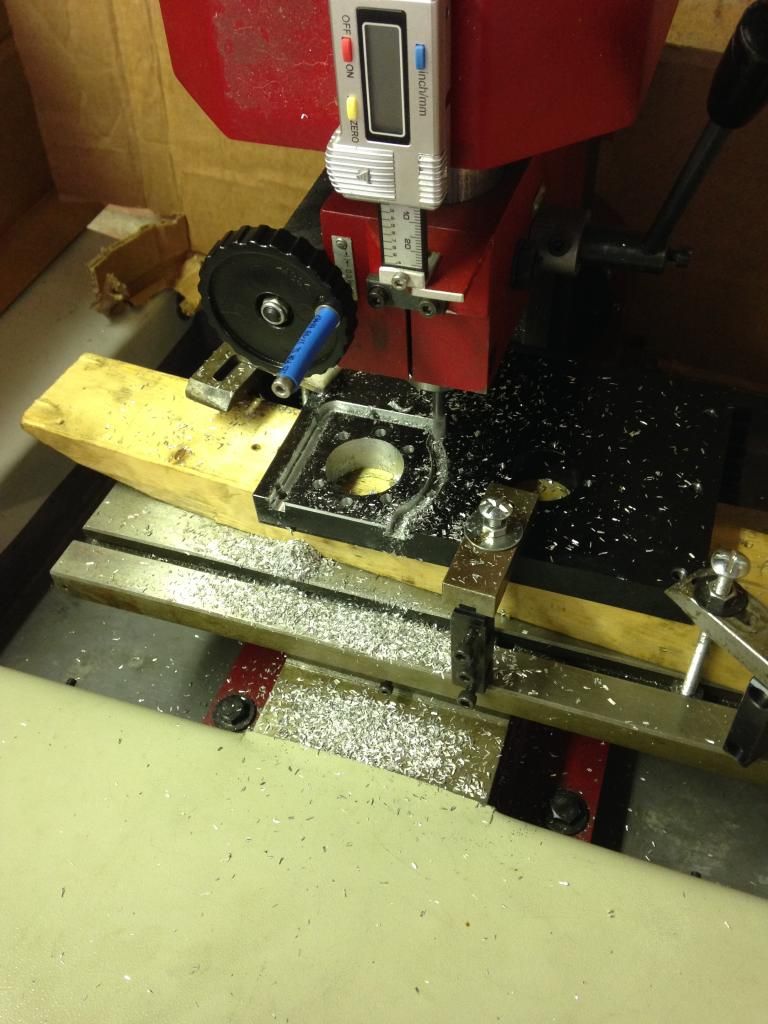 Quite stunning what the machine can now cut through took three hours to make this part start to finish quite happy with the result and again it just bolts together I have to do a bit of very accurate measurement next so I can make the bar that joins this plate to the head. |
|