|
|
Post by Roger on Jul 2, 2014 21:30:45 GMT
That's pretty quick, you're really getting into your stride now. Considering your spindle isn't well, the finish is pretty good. I like the fact that you can choose to have what curves you like without penalty. When you can cut any shape you can draw, it's nice to add radii to things you wouldn't bother with or nice curves like you've added to that part. It just takes away so many of the limitations of conventional kit.
|
|
|
|
Post by Doug on Jul 3, 2014 13:09:22 GMT
ok huge seniour moment here i am thinking what pulley ratio's i need so i can order a set for the new spindle motor. then slowly it comes into my head why am i buying a pully i have boatloads of plastic and a CNC mill.......what a muppet!
anyway the old rattly gearing is fixed (still rattles) and the final bits on the z axis are close to getting made,
after further investigation i have found the z axis is not very stable due to backlash (the head is jumping up and down the coloumb) so i am hoping that once the ballscrew is fitted the head should be alot more solid. It will never be a bridgeport but hopfully i can get a reasonable cut from it once its all tied down.
|
|
|
|
Post by Roger on Jul 3, 2014 17:04:21 GMT
Don't beat yourself up, after all, it's the same machine..... but it isn't. The list of things the machine can't do needs to be torn up. CNC mill, CNC lathe, engraving machine, maybe even a plasma cutter or 3D printer who knows what it could potentially do.
Gearing without special provision for backlash removal is always going to be noisy because there isn't a constant load in one direction. I had the same problem with the quill spline rattling until I made a friction element between the two. Sadly you can't do that with gears although you can have two side by side with a spring force between them.
I presume you're talking about making toothed belts for the new motor drive?
You'll find the new Z-axis ball nut is very rigid, it's a good thing you bought a nice chunky one, you won't regret that. Is there any adjustment on the Z-axis carriage?
Looking at what you have now, I can only see it being a lot better when you've finished your mods.
|
|
|
|
Post by Doug on Jul 4, 2014 5:14:22 GMT
Don't beat yourself up, after all, it's the same machine..... but it isn't. The list of things the machine can't do needs to be torn up. CNC mill, CNC lathe, engraving machine, maybe even a plasma cutter or 3D printer who knows what it could potentially do. Gearing without special provision for backlash removal is always going to be noisy because there isn't a constant load in one direction. I had the same problem with the quill spline rattling until I made a friction element between the two. Sadly you can't do that with gears although you can have two side by side with a spring force between them. I presume you're talking about making toothed belts for the new motor drive? You'll find the new Z-axis ball nut is very rigid, it's a good thing you bought a nice chunky one, you won't regret that. Is there any adjustment on the Z-axis carriage? Looking at what you have now, I can only see it being a lot better when you've finished your mods. Yes my plan is to add toothed belt to direct drive the spindle I will have to have a rethink and maybe use a lay shaft I will hold off on the spindle for a little bit as I am getting a bit buried with jobs at the mo. i put the new z axis together last night and had a mild panic atack when the motor would not turn it, I then remembered I had reduced the motor current so I raised it back up and it drives again the problem was the old screw was 1.5mm pitch the new one is 5mm so quite a jump, I hadn't even considered it I am lucky it turned out ok the whole assembly feels very solid now. 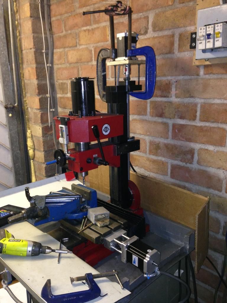 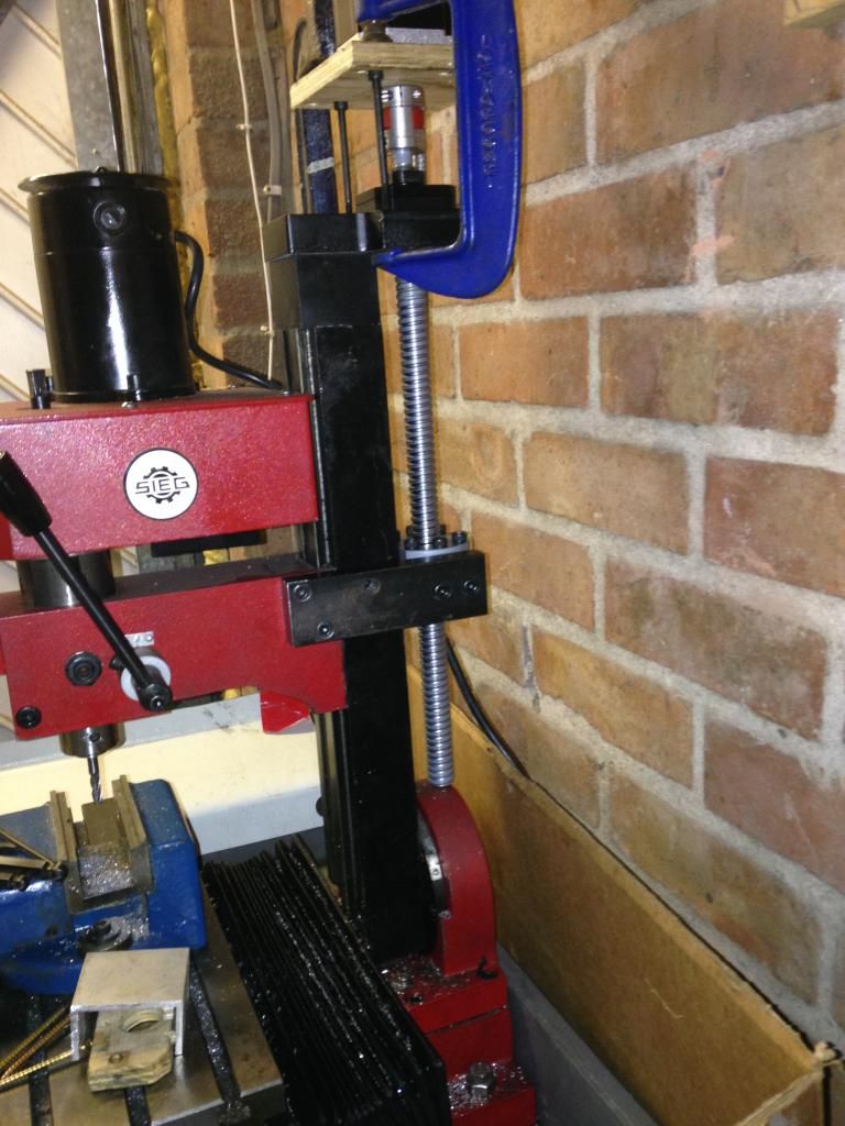 i will only know the real result when I cut the motor plate. the workshop need a really good clean up so I will probably focus on getting everything tidy before do any more work, I hate mess and it's starting to bug me a bit. While I wait for the delivery of the motor plate material I can get a lot of the guarding done. So lots of room for progress. Now it's all together I am going to start measuring the accuracy and see what I have to play with. not too long now I can get started on Speedy's blast nozzle. |
|
|
|
Post by Roger on Jul 4, 2014 6:58:44 GMT
That's good and solid, I expect that will be quite a bit more rigid than the original setup.
|
|
|
|
Post by Doug on Jul 4, 2014 10:02:04 GMT
That's good and solid, I expect that will be quite a bit more rigid than the original setup. yes its not flexing anymore i intend to put my clock on it and check the max diflection i also think a quil lock will help a bit as that too is a bit loose i am also going to add some spring washers to the lead screw bearings just to make sure there cant be any backlash in that area it should then be just down to the split nuts and any lateral play in the slideways. its a bit adictive chasing out errors i keep coming up with all sorts of crazy plans like a liner rail on the z axis and step back the current coloum to acommodate it with a 30mm thick steel plate on the machine base. the tables look like they will take rails quite well although it will increase the height a bit to allow a ball screw to be used. But for now i have a very capable machine imerging. albeit limited to its size once that point is taken into consideration then it works really well. a bit like my lathe i am so used to taking small cuts and taking it steady its only noticeable when you get on a "propper machine" you can tell its not very hard core. for instance the pic above the steel bar joining the head to the ballnut is 40mm wide 20mm deep i cut it with a 6mm endmill doing 1mm passes 50mm/min feed rate and it was about maxed out at that go any quicker and the finish goes first followed quickly by stalling the spindle. quite by sheer luck i have the drives set such that if the cutter stalls the drives go into currrent limit so i dont snap the tool (saved me at least 3 times so far when i have been pushing the envelope) the only down side to this is i loose position but its a small price to pay for the safety. |
|
|
|
Post by Roger on Jul 4, 2014 13:26:05 GMT
I've scribed a line on the quill locking lever so that I always tighten it to the same amount. You'll be surprised the difference there is between locked and unlocked. I always clock with the quill locked and the head as close to the height it will be when it's cutting.
You're right about chasing down errors, it is addictive. You can play with those clocking tests I mentioned when you're maxed out on that and get the right values for your backlash compensation. That ought to give you at least another 10microns accuracy for very little effort.
I'd play with it a fair bit before you go to any greater lengths. You could always sell it as a working CNC machine to fund a bigger one, you're sure to make a nice profit.
You're lucky that your machine gives up fairly easily, mine's quite happy to shear off a 16mm cutter if it feels like it, that's scary.
|
|
|
|
Post by davebreeze on Jul 4, 2014 21:34:52 GMT
When you say you replaced the old big strip, I'm guessing that it's not a tapered type then. What was the old one made of? I'm not sure Brass is a good choice, maybe a little research might come up with a better one? I had one of these Sieg X1L mills, the table wouldn't move smoothly and it was impossible to get a reasonable adjustment of the gibs. When I took them out they looked like they had been made with a knife and fork. They had a ground finish, but the roughest and most uneven I'd ever seen. A nightshift spent rubbing them down on emery on a flat surface improved things no end. |
|
|
|
Post by Doug on Jul 5, 2014 15:10:44 GMT
Been set busy got the wiring tidied up and the guarding made 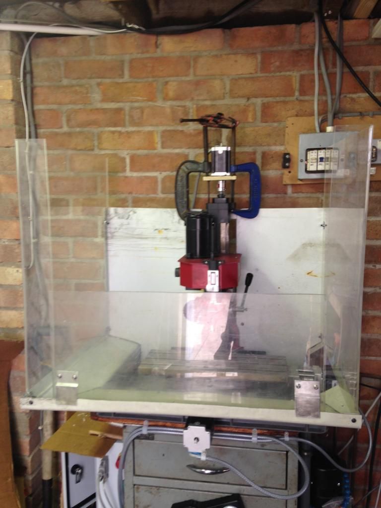 And its almost complete 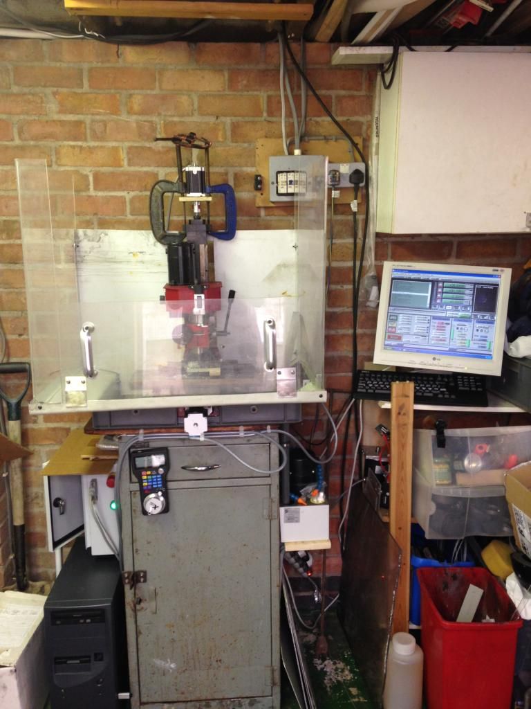 I have checked the backlash now I have the spring washers fitted and there is none (that I can measure) so below 10um. I am happy with that |
|
|
|
Post by Roger on Jul 5, 2014 15:38:05 GMT
I'm curious to know how you measured it, because you get different figures if you go about it in different ways.
The best way I found was to put a 2micron clock in the spindle and clock a hole as good as you can get it. The write a little program that lifts the clock clear, moves slowly to say X+0.5Y+0.5 then back to X0Y0 and Z back down. I then take down the readings at four points of the compass and repeat the exercise but going to X-0.5Y-0.5 this time. That will tell you what you've really got, and I bet it's at least a thou. Anyway, you can then put those values in and try again. I can get mine to repeat to within 5 microns ie two tenths whereas it was 30-40microns out before. I think that's well worth the effort when you get a minute.
|
|
|
|
Post by Doug on Jul 5, 2014 19:08:11 GMT
I'm curious to know how you measured it, because you get different figures if you go about it in different ways. The best way I found was to put a 2micron clock in the spindle and clock a hole as good as you can get it. The write a little program that lifts the clock clear, moves slowly to say X+0.5Y+0.5 then back to X0Y0 and Z back down. I then take down the readings at four points of the compass and repeat the exercise but going to X-0.5Y-0.5 this time. That will tell you what you've really got, and I bet it's at least a thou. Anyway, you can then put those values in and try again. I can get mine to repeat to within 5 microns ie two tenths whereas it was 30-40microns out before. I think that's well worth the effort when you get a minute. I don't have a 2um clock at home just use one at work 10um is enough for what I need at home, the way I test is the standard method (forward .1 backward .1 backward .1 then forward .1) it should then be back to zero the backlash is the resulting difference if you test with your method you will get various results depending on the cutting forces at the time so it will be different every time you do a diferent cut. i will try your method and see how much difflection I am getting  |
|
|
|
Post by Roger on Jul 5, 2014 20:14:31 GMT
I'm not quite with you on your method, do you have the clock touching all the time? You can't really do that with a 2micron clock, there's quite enough travel. I used a similar method but with it moving +/-half that distance slowly and checking the actual clock total movement which should have been 0.1mm. It's really odd that it didn't give the same result as the other method I used. I'm not sure why.
There are no cutting forces with my method, you just return to the same pre-machined hole and measure it. It's actually the same as your method really, it's just that you're doing it in two axes at the same time. It's fair comment to say that you'll get a different amount of backlash depending on the cuts you're taking when you're machining though. They ought to be small when you're finishing though, so it ought to come out close to the settings to find when there's no load.
|
|
|
|
Post by Doug on Jul 5, 2014 20:31:38 GMT
I'm not quite with you on your method, do you have the clock touching all the time? You can't really do that with a 2micron clock, there's quite enough travel. I used a similar method but with it moving +/-half that distance slowly and checking the actual clock total movement which should have been 0.1mm. It's really odd that it didn't give the same result as the other method I used. I'm not sure why. There are no cutting forces with my method, you just return to the same pre-machined hole and measure it. It's actually the same as your method really, it's just that you're doing it in two axes at the same time. It's fair comment to say that you'll get a different amount of backlash depending on the cuts you're taking when you're machining though. They ought to be small when you're finishing though, so it ought to come out close to the settings to find when there's no load. Right the first move forward .1mm no clock mounted then back one inc move set the clock 10 um or 2um just put about 30um on the clock and zero then back away one inc so same direction this should take you off the clock by about 0.07 then one move forward it should go back to zero if not then it shows the backlash it's basically loading up the lead screw/ballscrew in both directions and checking for differences it only shows the axis you check at the time, I will take a photo of the setup it should make sence then |
|
|
|
Post by Roger on Jul 5, 2014 20:48:45 GMT
Ok, I see what you're doing there. I think the similar method I tried first of all may have given different results because it was constantly on the move. I was just surprised that it was very different, by a factor of two or maybe a little more. I'd love to see if yours come out the same if you use your method and the hole clocking one. All these methods ought to come up with the same results but they don't. The speed you use in the move definitely has a bearing on it. This is where rails are so much better than what we've got. Dovetails are very stiff but they do have considerable stiction.
|
|
|
|
Post by Doug on Jul 5, 2014 21:52:48 GMT
Ok, I see what you're doing there. I think the similar method I tried first of all may have given different results because it was constantly on the move. I was just surprised that it was very different, by a factor of two or maybe a little more. I'd love to see if yours come out the same if you use your method and the hole clocking one. All these methods ought to come up with the same results but they don't. The speed you use in the move definitely has a bearing on it. This is where rails are so much better than what we've got. Dovetails are very stiff but they do have considerable stiction. Ok a bit of an update I have just retested (been machining all day) the test after the initial setup didn't show any backlash on the re test after I now have 0.03 in both x and y not very much but the backlash comp takes it below 10um I will keep checking and see how much it beds in. I am pretty happy with that result the machines we have at work move more than 60um during the day due to temperature and they didn't cost £650  |
|
|
|
Post by Roger on Jul 5, 2014 23:15:48 GMT
Now that's more like it, and as you say, with backlash compensation it can be very respectable. I think it's definitely worth having that 20microns, it costs you nothing more than a few measurements.
We used to keep the factory heating on 24/7 and turned the machines on for the best part of an hour before using them else they were constantly moving and you couldn't get the sort of tolerances we were looking for. None of the kit we had was expensive, but taking a few simple precautions allowed us to do things that we should never have been able to achieve.
|
|
|
|
Post by Doug on Jul 6, 2014 20:48:25 GMT
Ok been trying out engraving I have found the best way to do it and also showed up some issues I need to get the z axis to either move more freely or increase the power of the motor/transmission as I keep stalling the motor from time to time which looses position. Also for some reason if I zero the z axis the other ones jump a bit so I will try the G code offset in future see it that works better  |
|
|
|
Post by Doug on Jul 9, 2014 7:55:25 GMT
I fitted a pair of gas struts to the Z on my X1 with a view to reducing the effort for the stepper in a future conversion, I used 70 N struts, 40 or 50 would have been sufficient, it is now easier to wind the head up than down  Andy after taking the long way round i have decided to fit a gas strut to the z axis to help the z axis motor out which is strugling a bit with the new pitch on the ballscrew to this end i have worked out that i need about 8kg of force to just about neutralise the weight of the head. With this in mind I have adjusted a gas strut to give 8kg of force and i will fit it to the head. this should trim it up nicely. I have also identified i need a high speed spindle (a removable one) for when i do engraving or small detail work so i will look into that too. |
|
|
|
Post by Roger on Jul 9, 2014 8:24:12 GMT
I'd be inclined to use a lower force than necessary for a complete balancing, you may as well use the weight of the head to help with the backlash.
A lot of the high speed spindle designs are pretty grim technially. Kavo and Jaeger are pretty awful although they look good on the outside. Have a good look and find some users before you spend hard earned cash on something.
|
|
|
|
Post by Doug on Jul 9, 2014 9:50:29 GMT
I'd be inclined to use a lower force than necessary for a complete balancing, you may as well use the weight of the head to help with the backlash. A lot of the high speed spindle designs are pretty grim technially. Kavo and Jaeger are pretty awful although they look good on the outside. Have a good look and find some users before you spend hard earned cash on something. I am glad we are on the same wave lenght on this one the weight of the head is 12.5kg so i was thinking 2/3 of the load was about enough of an assist to bring the motor comfortably back into its working range (it is almost ok) while still getting the benefit of the patented gravity anti backlash system  |
|