|
|
Post by andyhigham on May 29, 2014 7:23:35 GMT
I have decided to start a new topic on myDenfrd Triac conversion to keep the other thread free for questions and answers So what have I got? The machine is in immaculate conddition, very little signs of use, built in 1985 The main motor is 375W with VFD. All 3 axis have 16mm ball screws with double nuts and angular contact support bearings to control end float. R8 spindle so I can share tooling with my VMC I have a programming / maintenance manual with mechanical and electrical drawings, another manual for off line programming with BBC computer. A set of brand new still in the wax endmills from 1/8" to 5/8", a set of step blocks and clamps/bolts. I will strip out the controller board, mini cassette deck, car type stereo cassete player and the little monitor. Replace the front panel and include keyboard and track ball or touch pad. The space vacated by the controller board will accomodate a Dell optiplex running win7 and a break out board/smoothstepper. I will try to use existing stepper drivers and motors for the moment 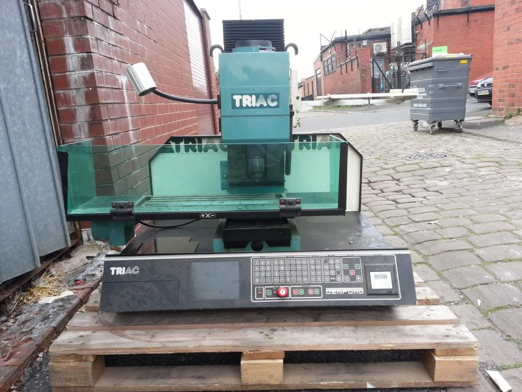 |
|
|
|
Post by andyhigham on May 29, 2014 7:30:49 GMT
Progress is being made but more setbacks seem to crop up. I have ordered the CM106-ESS breakout board with smartstepper card, THEN I looked at my Denford drawings. The CM106-ESS has 10 inputs, I have X,Y,Z axis home sensor and a limit switch at each end, low lubricant level, emergency stop. I make that 11 before I add in any control switches. I could omit the Lube level and just operate an LED and common up the end limits leaving me 3 inputs. The stepper drivers are Digiplan (Parker Hafina) SDS2 and SDS3, the step and direction inputs are 12v active low. I may need to do some interfacing with the CM106-ESS outputs which I believe are 3.3 to 5V. My stand / trolley is made, don't you just love unistrut. I was thinking about how to operate the Mach3. The obvious keyboard/mouse has its limitations, there is the risk of the keyboard and mouse getting damaged by swarf and coolant and trying to find a flat surface for the mouse. I saw a touch screen monitor advertised at a reasonable price, so I bought it, then realised it is 21 1/2 inch, Well I should be able to see it!!! My machine stand is finished, dismantled, taken home and re-assembled. Its a heavy brute. 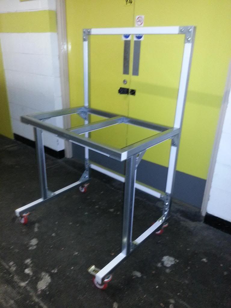 |
|
|
|
Post by andyhigham on May 29, 2014 7:39:11 GMT
Not a lot of progress to report I was caravanning at weekend. There is a little drop down door in the front panel, a car cassette player resided in there. I opened up the slot to fit MCBs. As a professional panel builder I hate the idea of just one fuse for everything. The home sensors are Namur type, they will not interface with the break out board, they require an amplifier. I have bought 3 conventional PNP inductive sensors. I have also built a simple transistor/resistor circuit to enable the break out boards 5v stepper control outputs to switch the 12v digiplan stepper drivers Ignore the values on the MCBs, they are just a handful I picked off the "ordered wrong" shelf  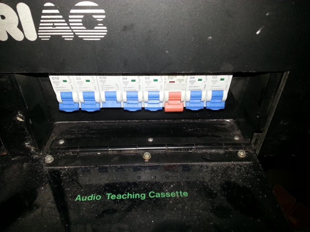 |
|
|
|
Post by andyhigham on May 31, 2014 16:12:55 GMT
This afternoon I moved the Triac from my garage to my workshop, easy yeah !!!
Assemble engine hoist and lift machine on to dolly, trundle from garage to back gate.
Disassemble hoist and re assemble in back yard, lift Triac and dolly up step and through gate.
Lift Triac and dolly onto decking and trundle through kitchen and into workshop.
Disassemble hoist and re assemble half in workshop and half in kitchen.
Lift Triac off dolly and wheel stand under it, removing some ceiling tiles to get the height.
Disassemble hoist again and store it away
I am going to drill the back panel of the machine and bolt it to the frame uprights as well as bolting the base to the frame.
The access panel to the oil pump is at the back of the machine, for better accessibility I am going to move the oil pump to the outside the column as on later machines.
|
|
|
|
Post by andyhigham on Jun 6, 2014 19:09:21 GMT
During odd moments I have been re wiring the control panel.
I have installed contactors for E.Stop, coolant supply and oil pump supply. MCBs for spindle, XYZ drives, PSU and transformer primary, 24v control circuit and 12v machine lighting.
This afternoon My smoothstepper motion control board arrived, I've connected up all bar the position inputs, I need some more pins for the connectors in the machine.
I am awaiting my engraving company doing my Traffolite plate for the back of the machine to mount sockets for monitor (mains,VGA and USB) mains inlet and coolant supply.
Also they are supplying a Traffolite fascia for the front.
Yesterday I received my Easy Change ER32 chuck, only it wasn't. The delivery note said ER32, the plastic tub containing it said ER32 but it was an ER25 inside. The supplier has promised to correct and check all his stock.
|
|
|
|
Post by ejparrott on Jun 7, 2014 19:58:41 GMT
Good service that. Bit of a nuisance, but I bet you fine you need one one day! My intention is to fit up with ER25, 20 and 16 in the fullness of time. The smaller collets will get in ore confined spaces. That will have to wait for the day I can afford them though!
|
|
|
|
Post by Roger on Jun 8, 2014 6:21:20 GMT
Take a look at this breakout board, it might be what you're looking for to increase the number of inputs you need. It looks like the simpler breakout boards all have the 25 way 'D' type connector on them, but you can make up an IDC cable to connect to the header on the spare port on the ESS, it's a one to one pin configuraion. |
|
uuu
Elder Statesman
   your message here...
Posts: 2,858
|
Post by uuu on Jun 8, 2014 8:16:18 GMT
Or look at the same firm's C10S board, where you can reconfigure outputs as inputs?
|
|
|
|
Post by andyhigham on Nov 4, 2014 20:26:13 GMT
Well I've been mega busy at work for a few months, so no time for playing with the mill.
I managed to find a couple of hours today, hoovered the dust off the control panel and decided that the Digiplan drives were far from ideal. I have bought 3 EM806 drives from Zapp Automation. They are big enough for me to upgrade to bigger motors if I wish, they also have a feature where they monitor the back EMF from the motor and use it to detect missed steps.
|
|
|
|
Post by andyhigham on Nov 7, 2014 19:18:31 GMT
I received my new stepper drivers so I did a bit of overtime yesterday evening and finished the control panel. The stepper drivers are the blue items middle left. next to them is the psu for the steppers. The inverter drive for the spindle is behind them. Front right is a second hand Dell PC running W7 and behind it the smoothstepper board. Along the front are the MCBs, control transformer, 24vDC psu, contactors for E.stop, spindle and coolant pump. I have left a space for a 4th axis drive and there is a socket on the back to connect the 4th axis. 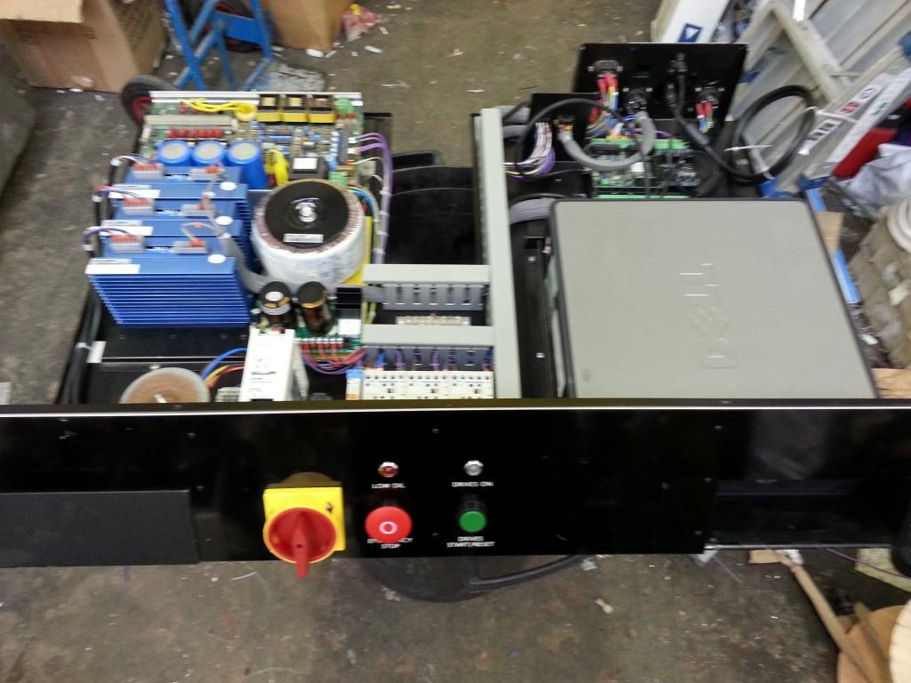 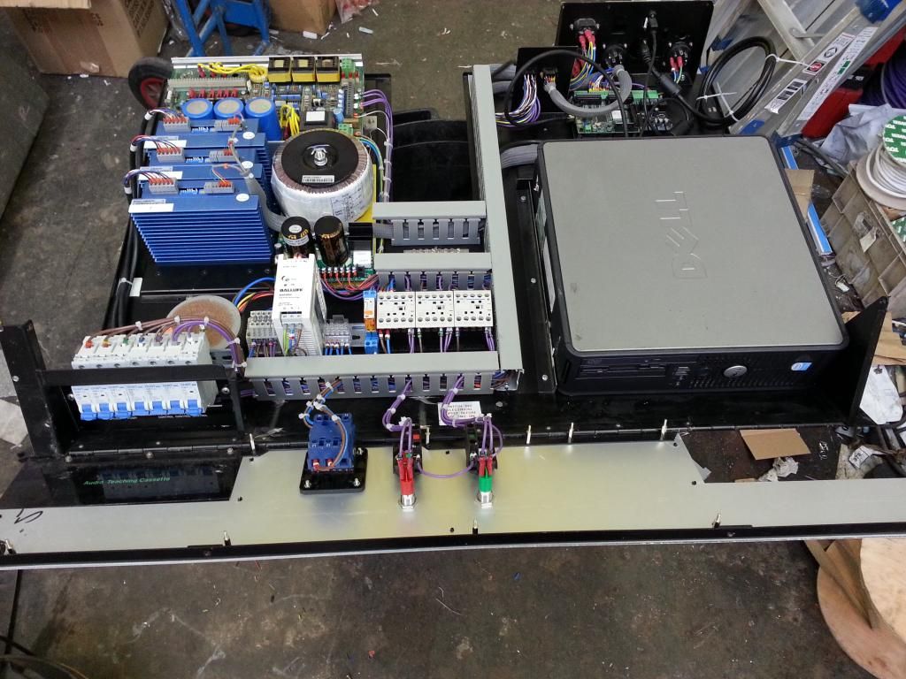 |
|
|
|
Post by Roger on Nov 8, 2014 17:41:16 GMT
That's really neat and tidy Andy, it should be good for another 20 years. That's a neat little PC you have there. I bought a similar sized unit that I got for our TV so my wife can get onto the Internet and all that. It's a handy size and very quiet.
|
|
|
|
Post by andyhigham on Nov 16, 2014 17:03:35 GMT
Well................... another step forward.........................and then another step backwards
I fitted the control panel back into the mill, connected everything and fired her up. I can make the table traverse x and y, the head will go up and down, the spindle will rotate but there is no response from the "home" proximity sensors. I bought PNP, I should have bought NPN. There is no mention of this in the control board instructions GRRRRRR
|
|
|
|
Post by Roger on Nov 16, 2014 17:27:42 GMT
That's annoying. Can you use uncommitted Opto-Isolated inputs for those so you can still use them? Some boards bring out both ends of the Opto with a series resistor so you can arrange them for either polarity.
|
|
|
|
Post by andyhigham on Nov 16, 2014 18:55:41 GMT
It's no big deal I will use the sensors on something else. I am struggling to control the spindle speed at the moment, I can get 0v or 10v and nothing in between
|
|
|
|
Post by Roger on Nov 16, 2014 19:37:10 GMT
That's odd, what interface board are you using? I presume you're using M03S1000 on the MDI to turn the spindle on and expect to get 1000RPM.
Mach3 uses a setup in the Motor Tuning and Setup page where you can select the spindle but I'm sure you've found that already. There's also a Pulley Selection function where you need to put the Max Speed for at least one ratio I think. Maybe you haven't filled something in there?
|
|
uuu
Elder Statesman
   your message here...
Posts: 2,858
|
Post by uuu on Nov 16, 2014 19:49:40 GMT
My spindle control board would not recognise the default PWM frequency from Mach3. I had to inrease it.
Wilf
|
|
|
|
Post by andyhigham on Nov 17, 2014 21:13:13 GMT
My mistake, I was assuming the speed override would control the speed. It actually only controls to a percentage of the pre set speed.
I just need to go through the stepper motor calibration and then I think I will be in a position to mill something soon, maybe out of MDF for a first try out
|
|
|
|
Post by andyhigham on Nov 17, 2014 21:19:48 GMT
I would have done some more playing tonight but I was told I mustn't operate machinery tonight. I have been relieved of an armful of blood
|
|
|
|
Post by andyhigham on Nov 18, 2014 20:55:55 GMT
I have now set up the stepper drives, I can put simple instructions in the MDI box and the machine moves to the co ordinates.
I need to download cam bam now and try to produce a simple object.
Am I right in believing once I have converted it to G code, I then load it into the Mach 3 and press go
|
|
|
|
Post by ejparrott on Nov 18, 2014 21:43:14 GMT
Yes, having first checked and set tool offsets and work offsets of course
|
|