|
|
Post by Roger on Nov 19, 2018 8:22:43 GMT
I'll second the call to bin the telescopic guards on the leadscrew, I dismantled the lathe before it even went on its stand so I could get rid of them. In my opinion they're horrible things, they affect the feel of the carriage and can affect the travel.
|
|
|
|
Post by Rob on Nov 19, 2018 22:01:14 GMT
I'm glad your set up seems to have worked. 300rpm on a cast iron faceplate? No wonder it was throwing dust around, I'd have been down around 100rpm on the outer reaches of that! As for not being able to get the saddle near to the work, those telescopic leadscrew guards are a b----y nuisance, take them off! Sooner or later, you'll need to to do a long piece of work and the tailstock end one probably restricts between centres travel by 3 or 4 inches. I'll admit it does seem a bit fast retrospectively, but rather than get the right surface speed for the outside edge and then be far too slow for the inner edge, I decided to pick a middle ground. I think I may have expired waiting for the cut to finish at 100 RPM, too, so perhaps not all bad. I have already removed all of the other guards, and on every other machine I've ever owned, but as I need to take things apart to get rid of the lead screw guards I haven't yet bothered. I'm lucky in that I have quite a long bed with 3 feet between centres, I can't imagine ever needing to turn anything that long, so it's only really a nuisance at the headstock end. I'll second the call to bin the telescopic guards on the leadscrew, I dismantled the lathe before it even went on its stand so I could get rid of them. In my opinion they're horrible things, they affect the feel of the carriage and can affect the travel. You're right Roger, quite a few times I've felt resistance and it's taken me a moment or two to twig that it's the guard at fault. On disengaging the feed when boring these wheels the carriage actually sprang back a little under the spring pressure of the guard! |
|
|
|
Post by ettingtonliam on Nov 20, 2018 8:01:16 GMT
]I'll admit it does seem a bit fast retrospectively, but rather than get the right surface speed for the outside edge and then be far too slow for the inner edge, I decided to pick a middle ground. I think I may have expired waiting for the cut to finish at 100 RPM, too, so perhaps not all bad. Its at times like that the variable speed drive on my current Denford 280, and previous Raglan lathe really comes into its own. Just move the lever on top of the headstock under power and alter the speed without stopping It will go from about 70 rpm up to about 350 before I have to stop to change into high gear. |
|
|
|
Post by Rob on Dec 5, 2018 21:59:42 GMT
No pictures in this update, but I do have some very interesting ones to come in the near future.
I have now made six driving crank pins, and I could easily make a seventh before I'm 100% happy. For whatever reason, this particular 1/2" silver steel is a right pain to machine - cuts always being oversize. By comparison, the 7/16th silver steel for the trailing and leading crank pins was a dream - bang on every time. Clearly the model engineering suppliers don't have consistent grades or heat treats on all their stock.
Anyway, on to the main topic of this post - frame stretchers.
Does anyone have any pictures/drawings of frame stretchers that would be typical of a GWR 0-6-0 and their usual location? My frames are currently far too flexible, particularly in the rear under the cab. I do have a brake cylinder bracket to go in, but this is small and I can't see it making a great deal of difference, so I'd like to include something more prototypical.
|
|
|
|
Post by Roger on Dec 6, 2018 8:27:22 GMT
No pictures in this update, but I do have some very interesting ones to come in the near future. I have now made six driving crank pins, and I could easily make a seventh before I'm 100% happy. For whatever reason, this particular 1/2" silver steel is a right pain to machine - cuts always being oversize. By comparison, the 7/16th silver steel for the trailing and leading crank pins was a dream - bang on every time. Clearly the model engineering suppliers don't have consistent grades or heat treats on all their stock. Anyway, on to the main topic of this post - frame stretchers. Does anyone have any pictures/drawings of frame stretchers that would be typical of a GWR 0-6-0 and their usual location? My frames are currently far too flexible, particularly in the rear under the cab. I do have a brake cylinder bracket to go in, but this is small and I can't see it making a great deal of difference, so I'd like to include something more prototypical. Hi Rob, Some materials are just a pain to machine. Silver Steel can be hard to take a small cut on, so I avoid those. Having a DRO on the lathe is a big help because it helps you divide the last three cuts into roughly equal depths. I usually leave say 0.2mm on the diameter for those three and make one final measurement just prior to the last one. Because you've already taken the spring of the cut into account and let it settle at the same amount you're about to remove, you have a good chance of hitting the exact size with the final cut. If you pore over the photos in my shared folder, you'll see at least two shots from below the rear buffer looking along the inside. You can also see glimpses of what's there on quite a few closeup shots from the sides. The GA seems to show that all the stretchers are folded plates, the only casting seems to be the one that brings the exhausts together and supports the smokebox saddle. You can't see what's under the cab floor, so you could add a plate there like I did. It doesn't have to be as massive as mine, although it's not important since it's not visible. 1501 is a complete mess between the frames, I personally wouldn't bother trying to model anything that can't be seen from the top. Even without the stretcher, it's pretty strong because you've got the gear frame as well as the pump stretcher. You'll be surprised at how much difference the gear frame and brake bracket makes. |
|
|
|
Post by Rob on Dec 7, 2018 21:56:08 GMT
Roger, I think it definitely needs something under the cab floor. Looking at the GA it looks like the brake cylinder is off the rear corner too, rather than mounted roughly central - there are many parts I'd like to take pictures of! These are the 'interesting' pictures I alluded to earlier: 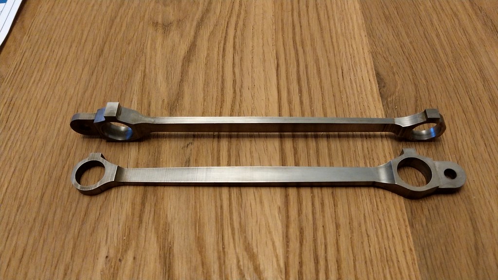 IMAG1682 IMAG1682 on Flickr 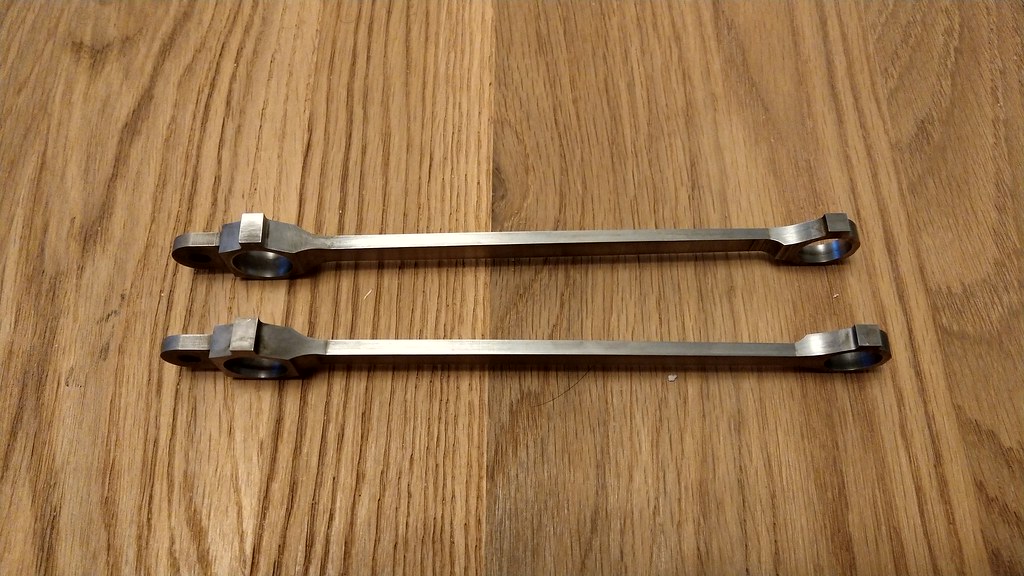 IMAG1684 IMAG1684 on Flickr 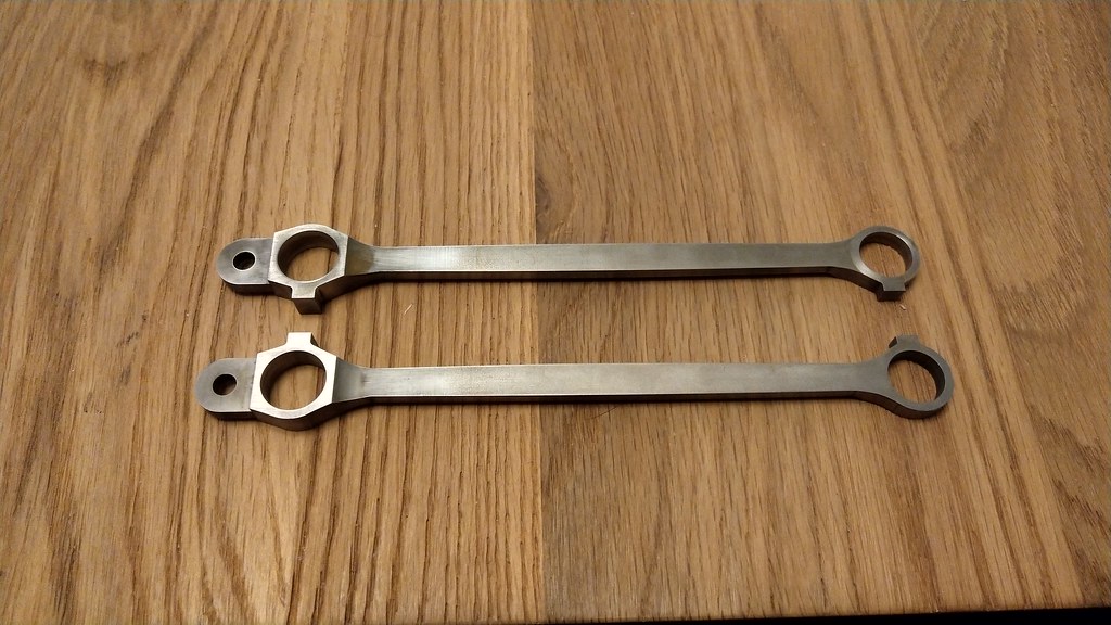 IMAG1685 IMAG1685 on Flickr I wish I could say I made these by hand filing. By chance I was chatting to a friend who runs a tool room, and he asked me if I had any awkward shapes I'd like cut with a wire eroder - these fish belly rods were the perfect candidate. I also think I might ask for his assistance with the expansion link. They do need a bit of tidying up and some edges blended as the eroder wasn't having the best of days, but still a thousand times improvement over what I'd have managed filing by hand. Once again, I'm left wishing I had access to any form of CNC. Let's just hope I measured the hole centres well enough... |
|
|
|
Post by Roger on Dec 7, 2018 22:29:16 GMT
Wow, those look superb. What a time saver too!
Don't worry too much about the hole centres, eccentric bushes will solve any issues with that.
|
|
|
|
Post by chris vine on Dec 7, 2018 22:38:03 GMT
You can also stretch or shrink them by 15 or 20 thou!!
Chris.
|
|
|
|
Post by Rob on Dec 7, 2018 22:44:48 GMT
I'm really pleased with them. I was worried my drawing would be too thin in real life, but they really look the part.
Chris - how so? Presumably with heat?
|
|
|
|
Post by Rob on Dec 9, 2018 23:26:24 GMT
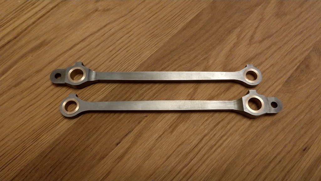 IMAG1691~3 IMAG1691~3 on Flickr 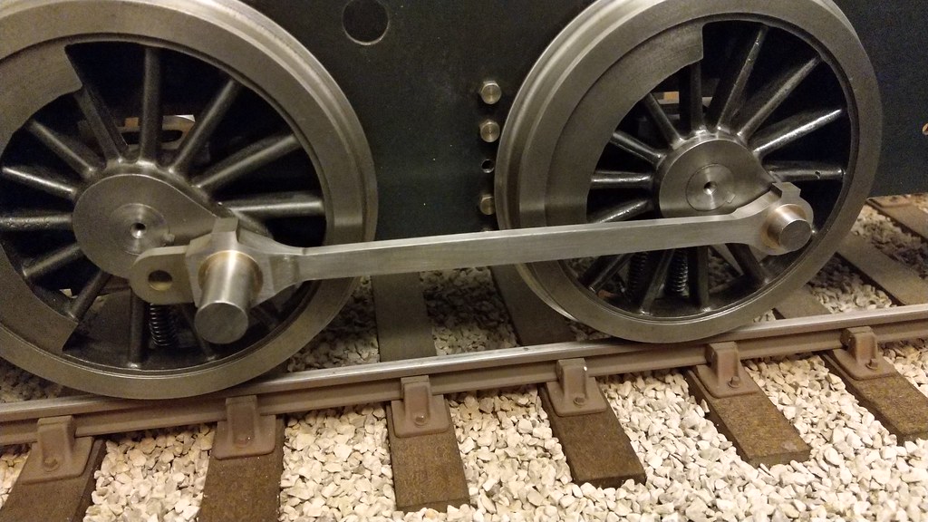 IMAG1689 IMAG1689 on Flickr They rotate nice and smoothly when each is fitted individually, but some tightness when both fitted, though not enough to prevent rotation. I reamed the driving bush, and bored the leading pin bush, so I can live with a little tightness given the minimal tolerances at the moment. |
|
|
|
Post by delaplume on Dec 10, 2018 0:49:13 GMT
That's looking really nice----It's worth considering Roger's eccentric bushes as they really do work..... Here's an everyday example of them in use}---------------------  It's those angled cross bracing........According to the T/V programme about its' construction the builders were faced with a severe temp difference between night and day to the point where the expantion was too much and the connecting pins wouldn't go in........... After a lot of "Thinking" some bright spark in the office came up with the eccentric bush idea which worked ( of course ) and there followed much back-slapping and champagne drinking !!..........I'm sat in front of the T/V saying}--- "Obviously they weren't on this Forum then" !! |
|
|
|
Post by Rob on Dec 10, 2018 19:55:19 GMT
Alan, given that they do rotate with what is effectively a 'reamed' tolerance I don't think they warrant eccentric bushes - there can't be much more than a thou or two clearance needed.
|
|
|
|
Post by Rob on Dec 16, 2018 23:09:21 GMT
This weekend was cold - 3 degrees in the garage on the Saturday. I managed to get it up to 7, but still a little on the chilly side! The focus for this update are the leading crank pins. I enjoy working on these little parts, they don't make much difference in the grand scheme of things but they're an essential part that make a visible difference. Nothing technically challenging here. I've delayed making these parts because I was hoping to find a solution that looks at least like it might be prototypical. I hate seeing large Phillips or slotted screws in models! I settled on a metric M4 Allen bolt. A nice a small hex head that doesn't look like it's too out of scale - about the best I could manage given the limited clearance behind the crosshead. I started by making the washers out of the end of one of the 9 spare axles I happen to have to hand which is the right OD. I drilled a clearance hole for the Allen bolt and created a 90 degree chamfer that allowed the bolt to sit flush with the surface of the washer. As the washer is only 1/16", I also needed a chamfer in the pin itself to allow the bolt to screw all the way home. The Allen bolts are of the black, high tensile variety, so I polished off the head with a little wet and dry on the surface plate to bring out the steel. I then drilled and tapped the crank pins. 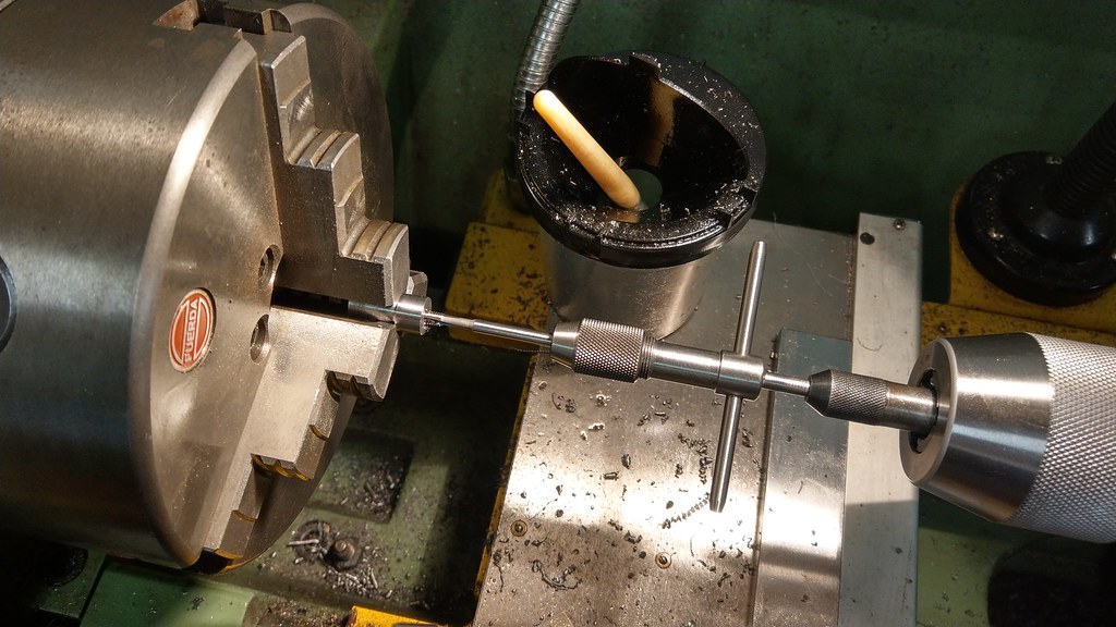 IMAG1696 IMAG1696, on Flickr 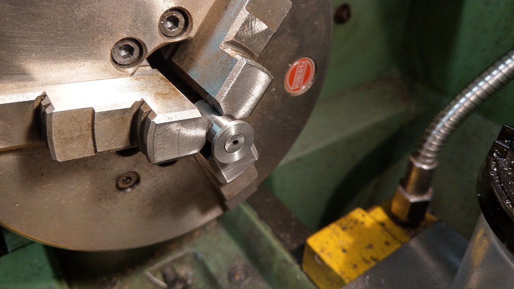 IMAG1697 IMAG1697, on Flickr 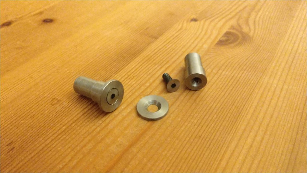 IMAG1700 IMAG1700, on Flickr Hopefully they don't look too incongruous. |
|
|
|
Post by Rob on Dec 22, 2018 22:09:30 GMT
This weekend it's the turn of the trailing crank pin nuts. Once again made out of one of the spare sets of axles. After the profiles were turned in the lathe, and the threads cut with yet another utterly rubbish ME tap, I transferred the stock to a collet block and milled the flats. 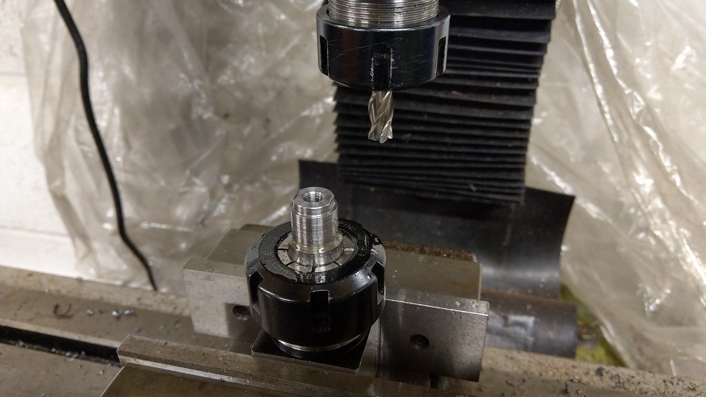 IMAG1703 IMAG1703, on Flickr Back to the lathe to part off the nut and start the process again. 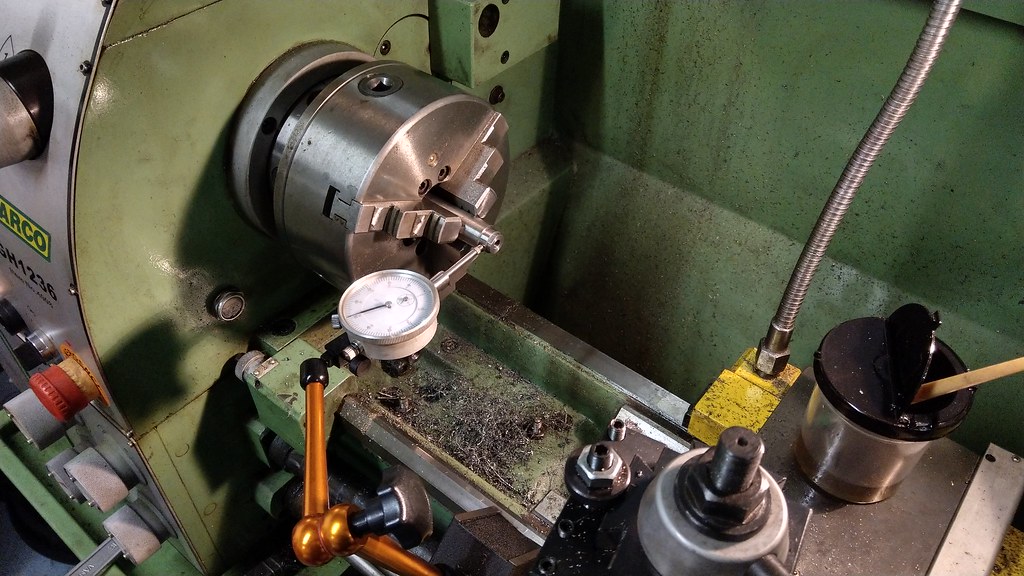 IMAG1705 IMAG1705, on Flickr I think I'm quite lucky with my 3-jaw as I'm usually able to repeat to 1 thou easily enough, and some times even down to the tenths. Finally, I used the crank pins with a few washers as a mandrel in order to chamfer the opposite side. 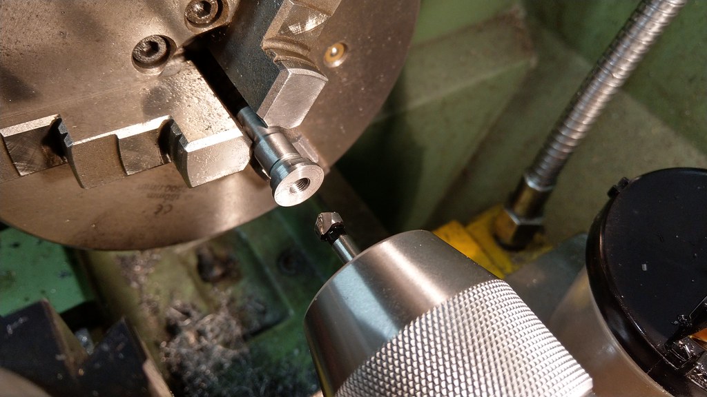 IMAG1706 IMAG1706, on Flickr Et voila! 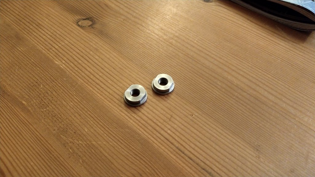 IMAG1708 IMAG1708, on Flickr Back to my rant about ME taps. Why can I buy high quality, branded metric taps that are spot on, for the same price as the cheap no-name taps the ME suppliers sell that are utter rubbish? I wonder if I should just make the switch to metric and be done with it. |
|
|
|
Post by Roger on Dec 22, 2018 23:02:21 GMT
IMAG1708, on Flickr Back to my rant about ME taps. Why can I buy high quality, branded metric taps that are spot on, for the same price as the cheap no-name taps the ME suppliers sell that are utter rubbish? I wonder if I should just make the switch to metric and be done with it. They came out really well Rob, a cracking job. I like your ER chuck for the vice. One day I might make a little fixture with two ears and an ER collet chuck so I can bolt it straight down to the table. I've used them on my turning attachment, and once set the one from the lathe on the bed, but that would be a useful addition. As for the above question, There's no need to use ME threads anywhere if you don't want to. I use this chart of Metric Fine Threads to select whatever size is suitable. There's always something close enough with a similar pitch. They include intermediate sizes that don't appear in the usual range of Metric Coarse Threads which makes selection even easier. |
|
|
|
Post by 92220 on Dec 23, 2018 11:05:12 GMT
I like that collet chuck holding fixture too.
As far as M.E. taps go, I have collected a fairly comprehensive set, from 1/8" up to 5/8", and my only grumble is that I couldn't get them in ground thread HSS. They all tap to correct size though. I just worry about breaking them off in a hole. One thing that is rarely mentioned when buying new, cut thread, carbon-steel taps, is that the very first use should ALWAYS be in mild steel. The cut threads on the carbon steel taps, have minute burrs, which ground thread taps don't. If you try to tap a soft metal like brass or aluminium, with a brand new tap, it WILL tap oversize. If you tap a piece of steel first, this removes those microscopic burrs and it will then tap correct sizE.
Bob.
|
|
|
|
Post by Rob on Dec 23, 2018 11:11:03 GMT
They came out really well Rob, a cracking job. I like your ER chuck for the vice. One day I might make a little fixture with two ears and an ER collet chuck so I can bolt it straight down to the table. I've used them on my turning attachment, and once set the one from the lathe on the bed, but that would be a useful addition. As for the above question, There's no need to use ME threads anywhere if you don't want to. I use this chart of Metric Fine Threads to select whatever size is suitable. There's always something close enough with a similar pitch. They include intermediate sizes that don't appear in the usual range of Metric Coarse Threads which makes selection even easier. Cheers Roger. Those little ER blocks are ace, I've used mine so much throughout this build I wouldn't be without one again. I also used that block to ensure the keyways on my axles were at 90 degrees to each other. I have one with a hexagonal block too, though I have yet to use it. I would like an ER chuck for the lathe too, but Warco seem to be out of the right size backplates at the moment. If I'm honest, what I'd really like is a 5C chuck instead, but I'm not sure if I really want to have to buy a whole new set of collets that are considerably more expensive than the ER ones, plus the more expensive chuck itself! And then are 5C collets really worth it for the model engineer if a full set of ER is already available? I am sorely tempted to make the switch to metric, I'll just have to have half a model in Metric, half in ME. Though, having said that, technically BA is metric too isn't it, so it's not that bad. I like that collet chuck holding fixture too. As far as M.E. taps go, I have collected a fairly comprehensive set, from 1/8" up to 5/8", and my only grumble is that I couldn't get them in ground thread HSS. They all tap to correct size though. I just worry about breaking them off in a hole. One thing that is rarely mentioned when buying new, cut thread, carbon-steel taps, is that the very first use should ALWAYS be in mild steel. The cut threads on the carbon steel taps, have minute burrs, which ground thread taps don't. If you try to tap a soft metal like brass or aluminium, with a brand new tap, it WILL tap oversize. If you tap a piece of steel first, this removes those microscopic burrs and it will then tap correct sizE. Bob. Bob, you must have a much better set than mine. Mine never seem to want to 'start' in a hole so the first few turns always ruin the outer threads. The squared ends always appear to be formed at an angle so they will not sit straight in my tap holders so that tapping with a spring loaded centre also results in malformed threads. I've already moaned about the dies earlier in the thread too. Conversely, the metric taps start first time and cut like they were going through butter, relatively speaking. The fit feels like it was a machined fit too, not tap and die! They even had me questioning my Starrett T-handled 'wrench'. I was thinking there must be something wrong with it if yet another tap sits in it at an angle. I was feeling a bit peeved given Starrett's reputation for quality and the price tag to match. But no, put in a metric tap and the 'wrench' holds it dead straight. Tune in tomorrow for more whinging!  |
|
|
|
Post by 92220 on Dec 23, 2018 18:25:58 GMT
That does sound as if your taps are dodgy.....possibly far eastern. Mine are all Apex Tap Co and Warrior taps which I bought some years ago. I don't often use a tap wrench. I usually do my tapping in the drill and hold the tap in the chuck, if it is a large size. If it is small diam. and may break, I use the manual tapping head that I can hold in the chuck. That way I can feel if it is binding, but the only time I make use of the square end is when I use the Eclipse chuck type hand wrench. Could you not make up a square shaped jig to hold the taps and use the flats of the square to regrind the tap square ends?
Bob.
|
|
|
|
Post by Rob on Dec 23, 2018 23:20:24 GMT
I definitely think they are far eastern. You're right of course, that's the model engineer's way to rectify the problem. To be frank, I'm not sure I can be bothered with something that's obviously of rubbish quality. I'm considering binning them and trying to find a different supplier. I didn't brave the garage today, I think the cylinders are next but it's a job that I need to work up the courage to start. Instead, I decided to focus on my 'floppy' frames by knocking up a design for a horizontal stretcher. This would sit between the cylinders at the base of the frame. Something similar but longer would fit under the cab - perhaps this one doubled. I'm thinking this would be a fabricated piece, perhaps using slots and tabs, made from 5 and 3mm hot rolled. I haven't brazed/silver soldered anything in about 15 years, so it would be good practise. 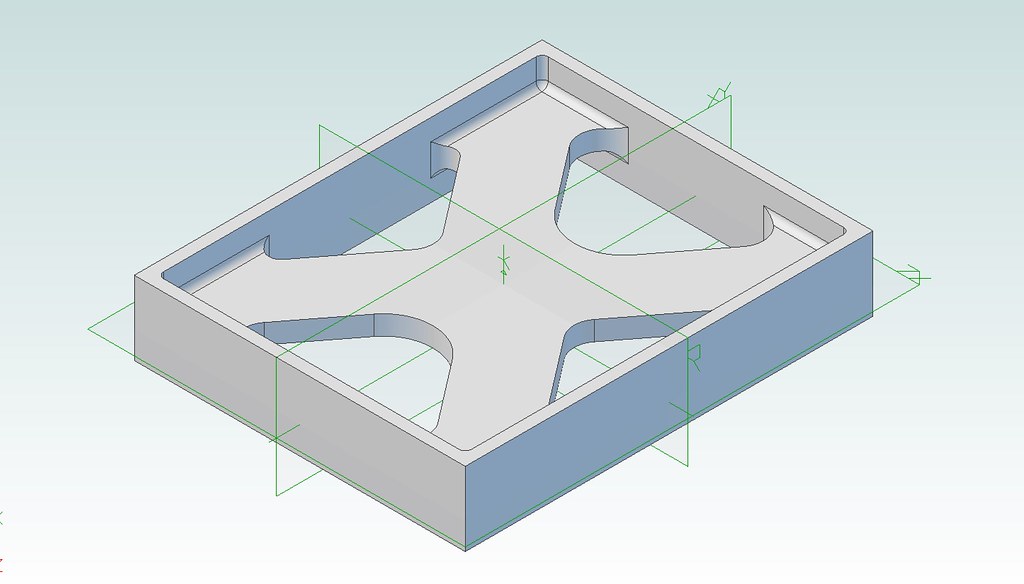 CylinderStretcher CylinderStretcher, on Flickr |
|
dscott
Elder Statesman

Posts: 2,438
|
Post by dscott on Dec 24, 2018 0:39:21 GMT
This looks lovely!
I was given a stack of half inch plates 6 inches square years ago and will be fitting a block
version of this under my cab to balance out the cylinders!!
I am doing a similar thing to my version of Asia but they have weights added in all sorts of places.
This is the only way to get any performance out of them. A heavy build on the boiler and tubes
will be considered like the Buldog design!
Love from
David and Lily.
|
|


