|
|
Post by David on Nov 5, 2018 22:12:02 GMT
When I saw the first axlebox picture I knew they must be split but I could not see where - great job!
|
|
|
|
Post by Rob on Nov 11, 2018 14:54:47 GMT
Thanks David. If only all things would go so well...
This weekend has been nothing but an unmitigated disaster.
Firstly, the car has blown an injector seal. Not such a big deal in the grand scheme of things. I can't be arsed to fix it myself, so it can go to the dealer on Monday.
Secondly, I've had three attempts to make a set of driving crank pins. For whatever reason this weekend, every finishing cut I make has been over size. Every roughing cut before hand has been bang on size, I know because I'm overly careful and like to measure how much my cuts are actually taking.
Thirdly, on finally achieving a decent driving crank pin and inserting it into my wheel, I discover that when drilling the holes something has caused the bore to head off centre at an angle. I might as well have drilled them with a hand drill, it's that bad. On both driving wheels. The ones where this is most critical. The other four wheels? Perfectly fine.
I don't know how best to correct this. I have contemplated setting them up again in the mill and running a milling cutter down through, but I have no idea if this will correct the problem or the cutter will just follow the direction of the original hole. One thing is for sure, I'm not making another set of wheels.
Times like these I feel like chucking the lot in the bin.
|
|
|
|
Post by Deleted on Nov 11, 2018 15:07:57 GMT
Hi, Rob..sorry to hear of your 'woes'....regarding the crankpin holes, if it was me I would use a cutter to machine oversize holes and fit a bush. The cutter if taken slowly won't follow the hole as it will be cutting metal all around, if that makes sense? It may be prudent to do the final bore for the bush after it's fitted to the wheel where you can be sure of the correct throw.
Regards
Pete
|
|
|
|
Post by Roger on Nov 11, 2018 15:42:12 GMT
Hi Rob,
These setbacks happen, don't let it get to you.
First of all, I'd tram the head to make certain the mill is machining vertically to the table.
If you don't have a drill guide for the crank pins then I think now is time to make one. You can make it over sized so you can put different hardened bushes in it.
Once you have a drill jig, you can set up the errant wheel with that clamped in place and clock up to the jig. Then I'd bore out the hole to clean it up, removing as little material as possible. Then you can either bore it to the next convenient size for a reamer and make a hardened guide bush to suit, or just leave it and make a crank pin to suit.
Alternatively, again using a drill jig, set it up on the faceplate of the lathe and use that for boring the hole.
It's vital to get all of the crank pin radii the same. I got one of mine wrong and wish I'd made a drill and reaming jig.
|
|
|
|
Post by Rob on Nov 11, 2018 16:19:17 GMT
Thank you for the ideas chaps.
Pete, would you opt for two or four fluted cutter?
Roger, I don't think the head is out as the other four wheels don't exhibit this problem, and they were all bored in the same setup. The 'off' angle is also front to back rather than side to side - I have no adjustment for that.
Given that I already have four other wheels with holes theoretically in the right place, I'm not sure how I could accurately make the drill jig to match the existing ones, or am I not seeing the wood for the trees? I think they'd match each other, but not necessarily all the others. I'm assuming the positioning of the hole is in the correct place as it was spotted with a centre drill, and the deviation has occurred once into the wheel. I was considering clocking on the very top the hole as a means of locating it.
I thought about using the lathe, but I don't have any boring tools small enough - the hole is 3/8", so I think my only option is the mill. What would you recommend for boring the hole?
I don't think I'll need to make bushes, I have a lot of room in the crank pin to allow for a bigger bore - the crank pin is 1/2".
|
|
|
|
Post by Deleted on Nov 11, 2018 16:32:39 GMT
Hi Rob
as the hole is already there I would just use whichever you have closest to the size cutter chosen, personally, I'd go for four flutes, others may disagree. This could even be an end mill as like I said the bulk of the hole is already there. I would use the lathe as suggested by Roger, you can hold the cutter in the tailstock chuck. I wouldn't clock from the already drilled hole, it may be slightly out. If you are happy with the other wheels, perhaps hold one of those in the chuck with a crankpin fitted and clock off that. You could then check each in the 4 jaw and use the same position for doing the two that are out, you'll then be confident of having all wheels with the same throw.
Pete
|
|
|
|
Post by Roger on Nov 11, 2018 16:38:58 GMT
Thank you for the ideas chaps. Pete, would you opt for two or four fluted cutter? Roger, I don't think the head is out as the other four wheels don't exhibit this problem, and they were all bored in the same setup. The 'off' angle is also front to back rather than side to side - I have no adjustment for that. Given that I already have four other wheels with holes theoretically in the right place, I'm not sure how I could accurately make the drill jig to match the existing ones, or am I not seeing the wood for the trees? I think they'd match each other, but not necessarily all the others. I'm assuming the positioning of the hole is in the correct place as it was spotted with a centre drill, and the deviation has occurred once into the wheel. I was considering clocking on the very top the hole as a means of locating it. I thought about using the lathe, but I don't have any boring tools small enough - the hole is 3/8", so I think my only option is the mill. What would you recommend for boring the hole? I don't think I'll need to make bushes, I have a lot of room in the crank pin to allow for a bigger bore - the crank pin is 1/2". I think I'd double check the radii of the other holes before going too far. If they are not on axles you can turn up a diameter in the lathe to sit them on and then clock a pin in the crank hole. That will tell you exactly what you have. You could do that with a pin in the wheel with the problem so you can check to see if the start of the hole is actually in the right position. My concern is that without a guide bush any oversize hole will follow the one that's already there. You can grind a boring bar from a piece of round HSS or from Silver Steel and harden it. Alternatively, use an old 2-flute cutter as a boring bar. Boring something set up to the exact radius will make sure the hole goes where it's centred. |
|
|
|
Post by simplyloco on Nov 11, 2018 16:48:50 GMT
Thank you for the ideas chaps. SNIP I thought about using the lathe, but I don't have any boring tools small enough - the hole is 3/8", so I think my only option is the mill. What would you recommend for boring the hole? I don't think I'll need to make bushes, I have a lot of room in the crank pin to allow for a bigger bore - the crank pin is 1/2". A 3/8" hole is HUGE!!! If you can put the wheel in the lathe but don't have a boring bar, then I would make and use a 'D' Bit out of 3/8" silver steel. You will get a straight, accurate hole. John |
|
stevep
Elder Statesman

Posts: 1,070
|
Post by stevep on Nov 11, 2018 20:41:34 GMT
I have a fierce mistrust of drilling jigs, as I have been unsatisfied with the results in the past. As a result, I now bore all my crankpin holes in the lathe.  As my axles have a keyway machined in them, the stub axle used to mount the wheel is similarly equipped, and ensures everything is in line. |
|
don9f
Statesman
 Les Warnett 9F, Martin Evans “Jinty”, a part built “Austin 7” and now a part built Springbok B1.
Posts: 960 
|
Post by don9f on Nov 11, 2018 22:32:14 GMT
Hi, regarding Roger’s suggestion of using a two fluted slot drill.....I did this recently when I needed to bore a small hole. I reamed a 1/4” hole through the length of a piece of 3/8” square bar, then slit one face of it lengthways with a slitting saw (or was it a Junior Hacksaw?). A 1/4” shank slot drill was then inserted into the hole and orientated such that when clamped in the toolpost (slit horizontal), one of the cutting edges was presented to the work just like a boring bar would have been.
Hope that rambling makes sense....too late to go out to take photos!
Cheers Don
|
|
|
|
Post by Rob on Nov 11, 2018 23:15:32 GMT
Don - that does make sense!
I wish I'd done these in the lathe now too, though I couldn't use the keyway to align mine as I used my crank pin holes to align my keyway!
I can't think how I can accurately set these wheels up in the lathe unless I clock off the existing hole. Usually I'd mark the hole with a centre drill in the mill, and then use the dual dead centre trick to clock that true with the lathe axis.
I've tested the crank pin location with a test coupling rod made from some 5mm scrap plate. I think they must be in the right place as I can rotate the driving and trailing wheels a full revolution with no binding, and the same coupling rod fits both sides.
I'm thinking of milling a new hole with a 10mm slot drill, that'll make the hole 19 thou over size. Clock the centre bore of the axle then use the DRO to set the right offset. I suppose it depends on how much you can trust the DRO to be repeatable. In theory, it should be spot on. In reality, who knows.
|
|
|
|
GWR 15xx
Nov 11, 2018 23:42:22 GMT
via mobile
Post by Roger on Nov 11, 2018 23:42:22 GMT
Just a thought on setting the radius on the lathe. You could make a bar that fits in the tool post that has a location piece picking up the centre of the wheel. You can clock around that with the clock attached to the faceplate. Then you can zero the cross slide and wind it over to the required radius. Then the wheel can be fitted to the location piece and tightened to the faceplate.
Hopefully that makes sense.
|
|
|
|
Post by David on Nov 11, 2018 23:48:13 GMT
Plenty of other advice here so none from me. Just writing to offer moral support! I hope a new day brings back the enthusiasm to set things right.
|
|
stevep
Elder Statesman
Posts: 1,070
|
Post by stevep on Nov 12, 2018 8:46:47 GMT
Rob,
My approach would be to make yourself a stub axle with a keyway, and then set up one wheel, clocking the crank pin hole you have already drilled. As you are going to open the hole up, and either fit a sleeve or a crankpin with a slightly larger diameter where it goes into the wheel, you can open the hole up to the necessary size by boring.
Without moving the stub axle, the other five wheels can be machine likewise, knowing that all the crank pins will be in the same relative position to the keyway. (There is no necessity for them to be in line).
|
|
|
|
Post by Rob on Nov 16, 2018 22:36:56 GMT
Not much to report. Zero enthusiasm to take fifteen steps backwards unfortunately. I hope I don't need to remove the wheels again. So much for my earlier optimism. 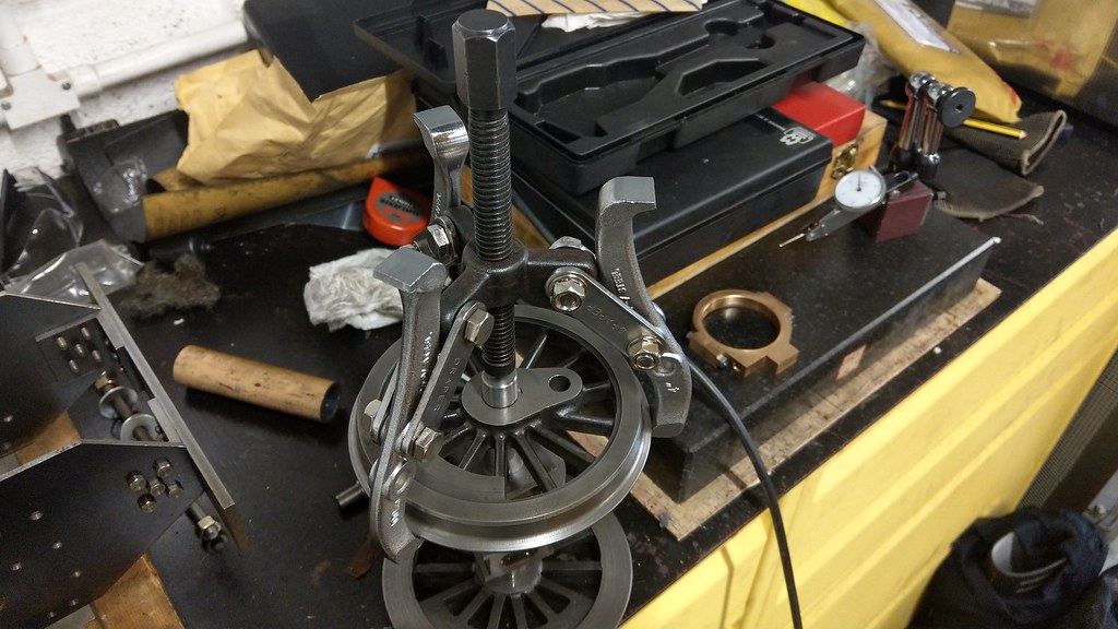 IMAG1663 IMAG1663, on Flickr |
|
|
|
Post by Roger on Nov 17, 2018 8:24:52 GMT
Hi Rob,
I know it's hard, but keep plugging away. There are no quick fixes to these things, you just have to dig deep and do whatever it takes. That's a great looking wheel set with very few issues. Once your sorted it out, you'll find your enthusiasm again.
|
|
|
|
Post by Rob on Nov 17, 2018 19:17:27 GMT
I know Roger, I'm just being petulant. Enthusiasm is naturally low at this time of year in the cold and the dark anyway. I'd just like to be at the stage where I can leave the chassis alone and start adding bits to it. Today I have been looking at setting up the wheel on the face plate. Having never used the face plate with this lathe, I was curious to see how close it was 'out of the box'. It clocked in at roughly 10 thou run-out. I was expecting it to be better than that. I stoned the spindle nose and cleaned the bore on the face plate a few more times to make sure there was absolutely nothing pushing it out, and managed to get it down to about 3-5 thou run-out. Closer, but not good enough. Skimming was difficult as the carriage on the lathe struggles to get close enough due to the lead screw covers. I had to use more overhang than I would otherwise have liked to get close. This is about as close to the headstock as I can get. 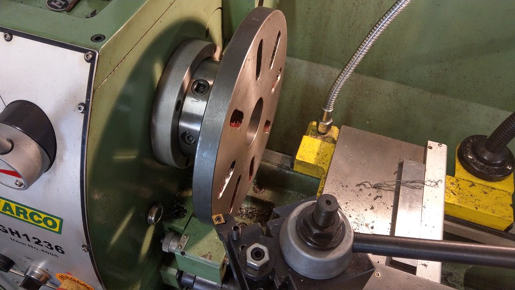 IMAG1665 IMAG1665, on Flickr I made the cut at 5 thou depth at 300 RPM, with the slowest feed my machine has. I immediately regretted that decision as I was stood there with the vacuum cleaner to stop the lathe getting covered in dust for about 15 minutes. 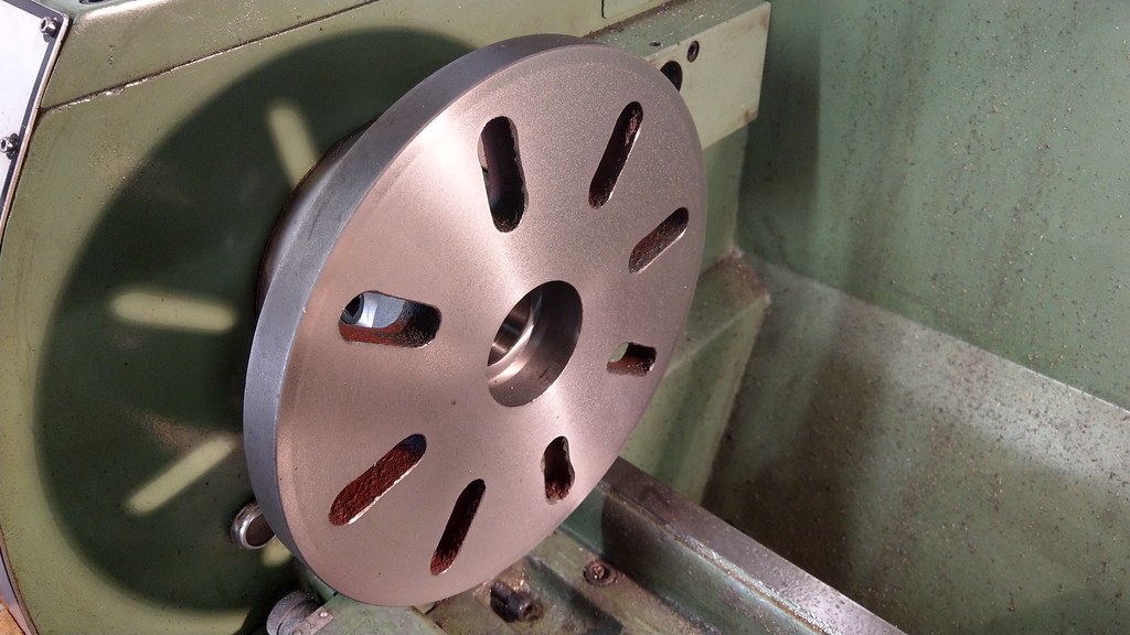 IMAG1666 IMAG1666, on Flickr Interesting change in finish near the outer edge - I expected to see this a number of times as surface speed reduced, but it was surprisingly consistent from that point onwards. As you'd hope, the face plate was now spot on. This was my method for clocking the crank pin hole. 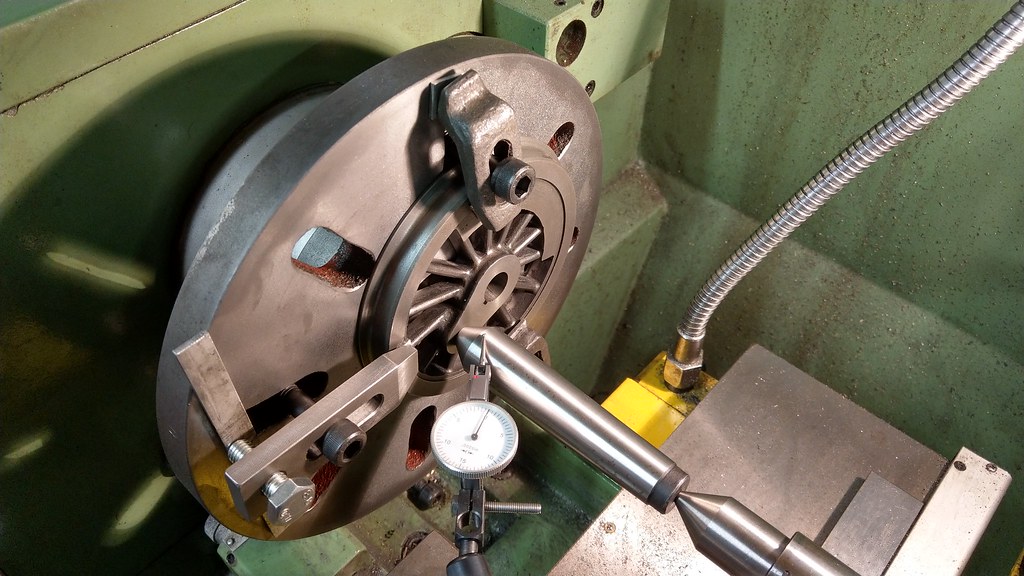 IMAG1667 IMAG1667, on Flickr With this method I'm measuring a few tenths out. I don't think I can get much closer than this as I end up pushing it back out further when I start chasing those tenths. I tried sweeping the inside of the bore, but I can't get a consistent reading with the needle constantly jumping. I'm not sure if this will be good enough, but I can't think of another way of getting it in position. I haven't started cutting yet, it took me all afternoon just to get to this stage. I'm fairly confident the holes in these wheels are in the right position as the test coupling rod allows the wheels to rotate a full revolution without binding. I'm not going to attempt to re-bore the other 4 wheels as I'm worried I might make something worse, so I'll do only the two drivers. Hell, I might still make the drivers worse! I also have less room for larger bores in the leading and trailing wheels due to the smaller O/D of the crank pins. |
|
|
|
Post by Rob on Nov 18, 2018 22:29:58 GMT
First of all, the problem I'm trying to correct. As I mentioned, I'd have achieved better results with a hand drill. Drunk. 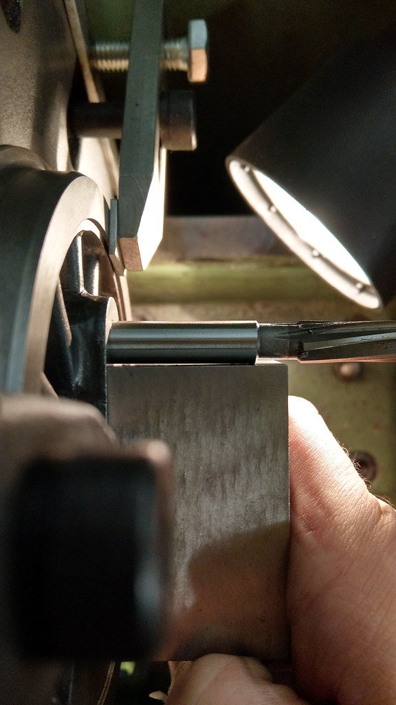 IMAG1669 IMAG1669, on Flickr And the boring 'bar' I re-purposed. I made this years ago for use in the Myford. It probably features in earlier photographs on this thread. I needed a little more clearance to fit in the 3/8 hole, so had to grind away quite a bit more. Crude, but it works. 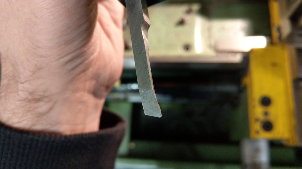 IMAG1677 IMAG1677, on Flickr 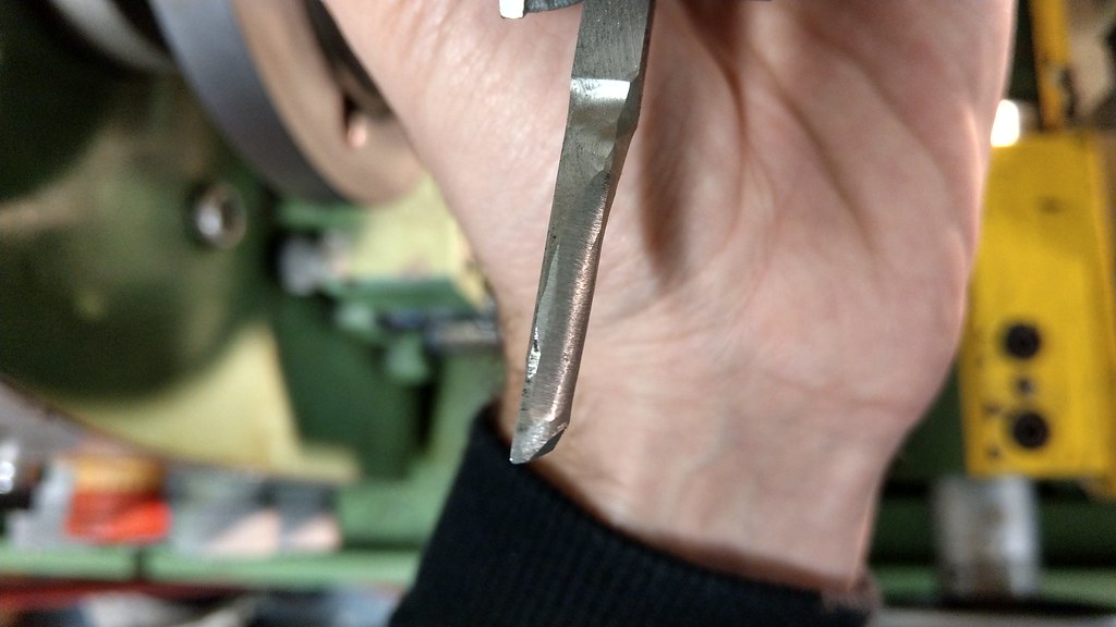 IMAG1678 IMAG1678, on Flickr Once again, to get anywhere near the work I needed an enormous overhang. 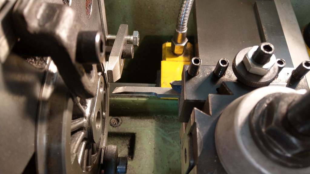 IMAG1672 IMAG1672, on Flickr 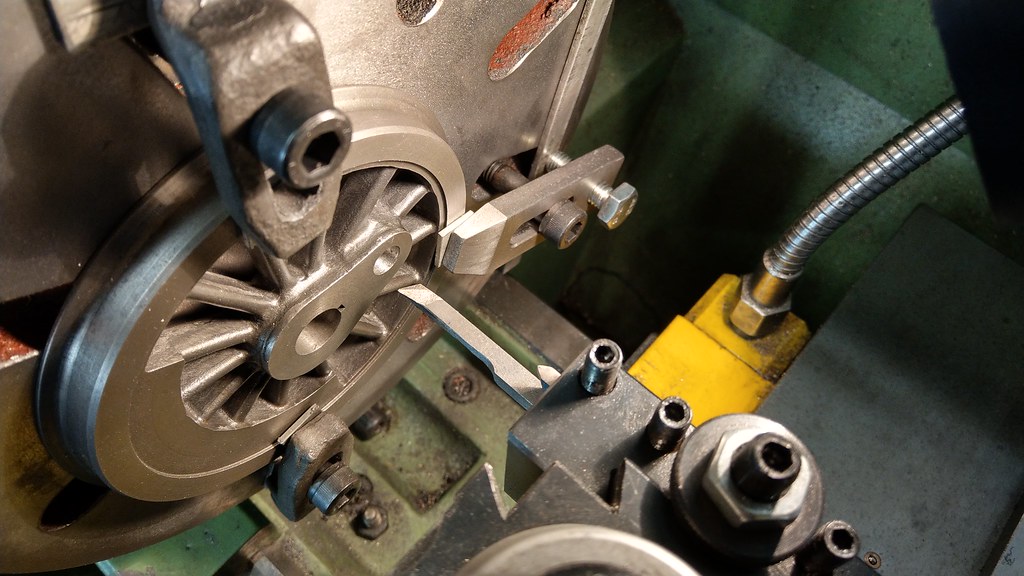 IMAG1670 IMAG1670, on Flickr With the DRO I was able to sneak up on the size easily, taking as little as a few tenths at a time right at the end. The biggest cut I made was 1 thou, I really didn't want to push my luck. I also kept the RPMs right down at 280 so I could see how the cut was progressing. The holes are now 0.389, up from 0.375. Odd size? Perhaps - but I have no way to accurately measure holes this small, so I used the end of a drill as a plug gauge. The holes are at least straight now. Whether or not they're still in the right position remains to be seen. I need to make my 5th and 6th driving crank pins first. |
|
|
|
Post by Roger on Nov 18, 2018 23:25:26 GMT
Excellent! Glad to see you're back on track. Who cares what the absolute size is as long as the pin fits!
I've learned not to dwell on what at first appears to be a disaster, I just try to quickly move on to a well executed fix and put it down to experience. That's a really good setup.
|
|
|
|
Post by ettingtonliam on Nov 19, 2018 0:21:09 GMT
I know Roger, I'm just being petulant. Enthusiasm is naturally low at this time of year in the cold and the dark anyway. I'd just like to be at the stage where I can leave the chassis alone and start adding bits to it. Today I have been looking at setting up the wheel on the face plate. Having never used the face plate with this lathe, I was curious to see how close it was 'out of the box'. It clocked in at roughly 10 thou run-out. I was expecting it to be better than that. I stoned the spindle nose and cleaned the bore on the face plate a few more times to make sure there was absolutely nothing pushing it out, and managed to get it down to about 3-5 thou run-out. Closer, but not good enough. Skimming was difficult as the carriage on the lathe struggles to get close enough due to the lead screw covers. I had to use more overhang than I would otherwise have liked to get close. This is about as close to the headstock as I can get. IMAG1665, on Flickr I made the cut at 5 thou depth at 300 RPM, with the slowest feed my machine has. I immediately regretted that decision as I was stood there with the vacuum cleaner to stop the lathe getting covered in dust for about 15 minutes. Interesting change in finish near the outer edge - I expected to see this a number of times as surface speed reduced, but it was surprisingly consistent from that point onwards. As you'd hope, the face plate was now spot on. I'm glad your set up seems to have worked. 300rpm on a cast iron faceplate? No wonder it was throwing dust around, I'd have been down around 100rpm on the outer reaches of that! As for not being able to get the saddle near to the work, those telescopic leadscrew guards are a b----y nuisance, take them off! Sooner or later, you'll need to to do a long piece of work and the tailstock end one probably restricts between centres travel by 3 or 4 inches. |
|


