rrmrd66
Part of the e-furniture

Posts: 339 
|
Post by rrmrd66 on Oct 12, 2017 15:53:39 GMT
Evening all Back after a short break. Worked out why I couldn't post pics in the end. Any how on with the build which I have spent a huge amount of time on. Remember that this is my first ever engine build. The eccentric straps have to be cut in half, reduced and machined to bring them to near round before boring in the lathe. I left the height of the top portion about 12-15 thou oversize to allow for eventual trimming along with the connecting rods that join up to the expansion link. 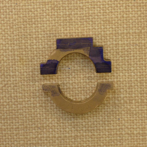 P1010161 P1010161 by Malcolm HARWOOD, on Flickr The eccentric sheaves are a bit of a b****r. They have to be cut from 2" dia MS bar. That should test your parting off skills as it is easier to do 5 at once with a form tool and then part off. The form tool should generate a true cylindrical surface. Mine did not so a bit of fettling with the parting off tool (being fed sideways!) soon solved the slight taper i managed to get. The split rings I made below allowed me to grip the sheaves in the four jaw for facing off to finished width without crushing the 60 thou shoulders or damaging he bearing surface. 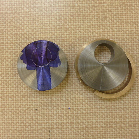 P1010148 P1010148 by Malcolm HARWOOD, on Flickr Next came the connecting rods, DY suggests a fabrication with brazing. I chickened out and milled mine from 1/2" sq. MS bar. The clevis at the end I did with a 1/4"slot drill. 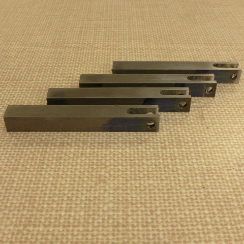 P1010167 P1010167 by Malcolm HARWOOD, on Flickr After milling I marked the centre for the hole that will affix to the expansion link. I am aiming to get the 4 5/8" centres (not the 4 7/8" as DY says, I think he may have added up wrong) spot on. My thanks to Julian for pointing this out and running all the dimensions through the Bill Hall spread sheet. Do you like my newly acquired analogue height gauge. It works with ball bearings. Brilliant. Never seen one before. It was a gift from a friend, along with the surface plate. Thanks Peter. 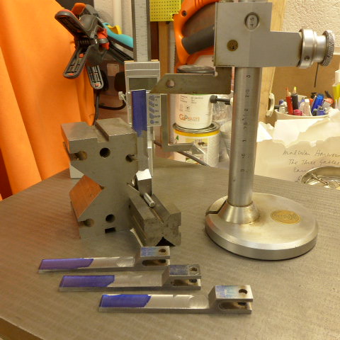 P1010168 P1010168 by Malcolm HARWOOD, on Flickr The foot for the connecting rod was made from MS bar. I was not keen on DY's butt joint idea so made a more positive location. To my delight the brazing went fwell achieving good penetration. 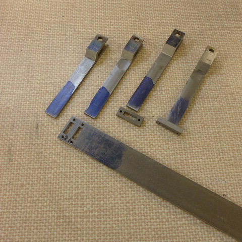 P1010169 P1010169 by Malcolm HARWOOD, on Flickr That's all for now. more later Thanks fr reading Malcolm |
|
rrmrd66
Part of the e-furniture
Posts: 339
|
Post by rrmrd66 on Sept 29, 2017 15:22:08 GMT
Evening all
Just spent a frustrating hour trying to update my build diary with Flickr pictures but cannot get them loaded into the post.
I am on a Mac
Have got Speedy Rodger"s guide. This worked fine last post.
Anybody else having problems? Has anything changed since my last post in August
Cheers
Malcolm
|
|
rrmrd66
Part of the e-furniture
Posts: 339
|
Post by rrmrd66 on Aug 23, 2017 19:24:52 GMT
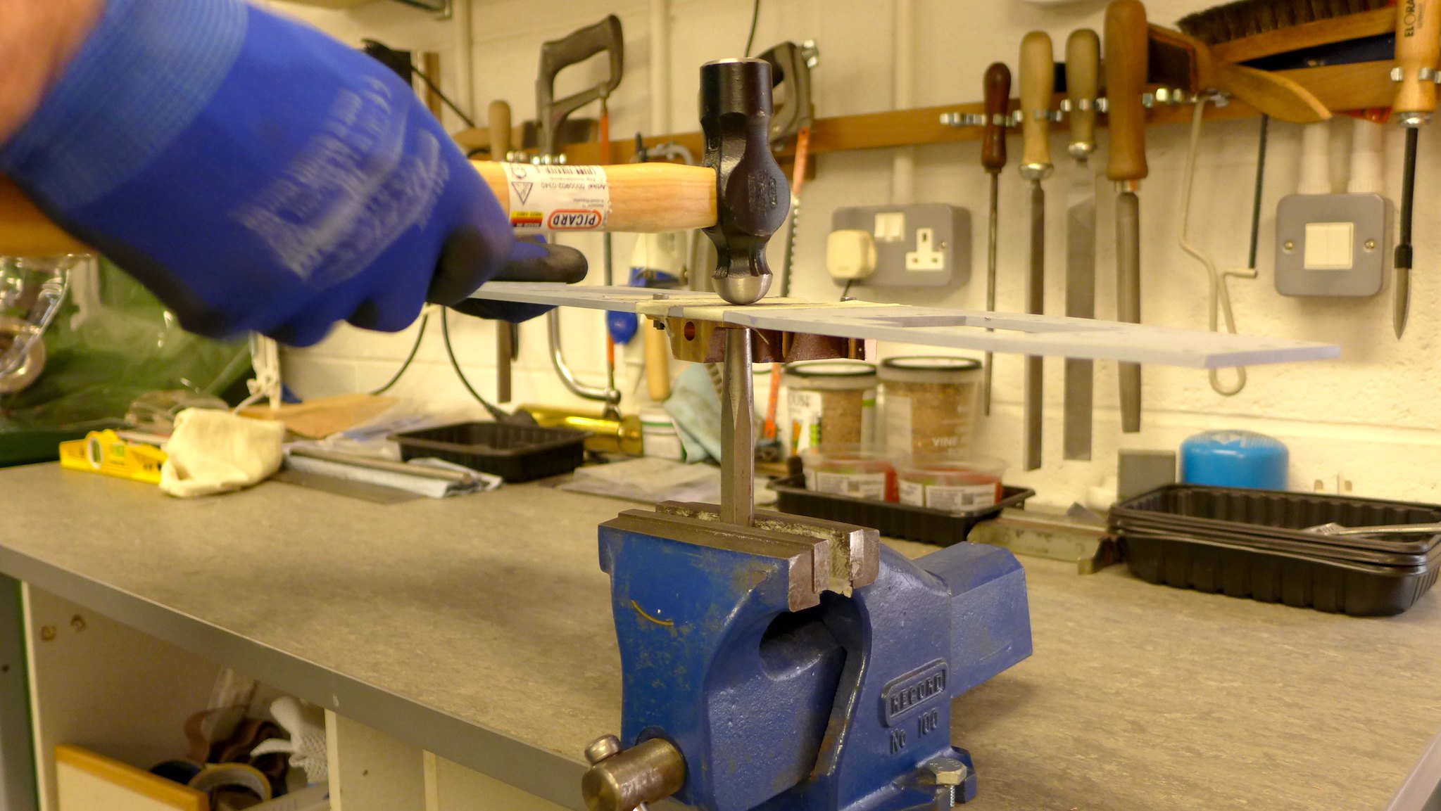
Evening everybody. Further progress to report on the Hunslet build. The cast iron wheel casting was faced in the four jaw chuck. The outer diameter is as received from the foundry, fettled with a hand grinder. The four jaw grips on the conical portion of the wheel allowing the outer flange diameter to be turned true. A centre drill and gradual opening up to 18.5mm diameter (cheaper than a 47/64" dia. drill) and finishing off with a 3/4" dia hand reamer. Can't remember if this is good practice but have not got a 3/4" machine reamer and the 3/4" dia. axle was a good fit. 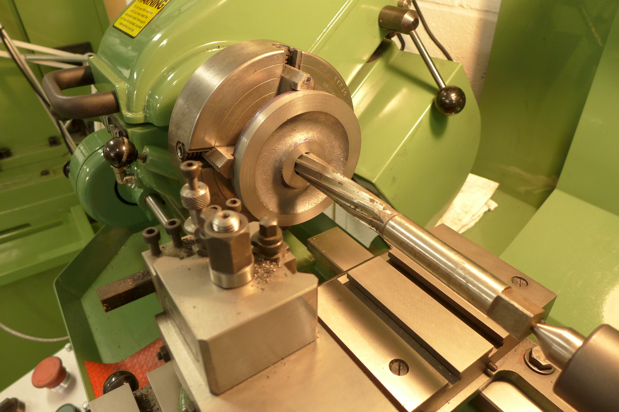 P1010141 P1010141 by Malcolm HARWOOD, on Flickr Next, I purchased a 2MT hardened adaptor with a "soft end" and turned it to 3/4" to provide a location for the wheel in order to face "the other side" and turn the slight conical tire and add a bevel. 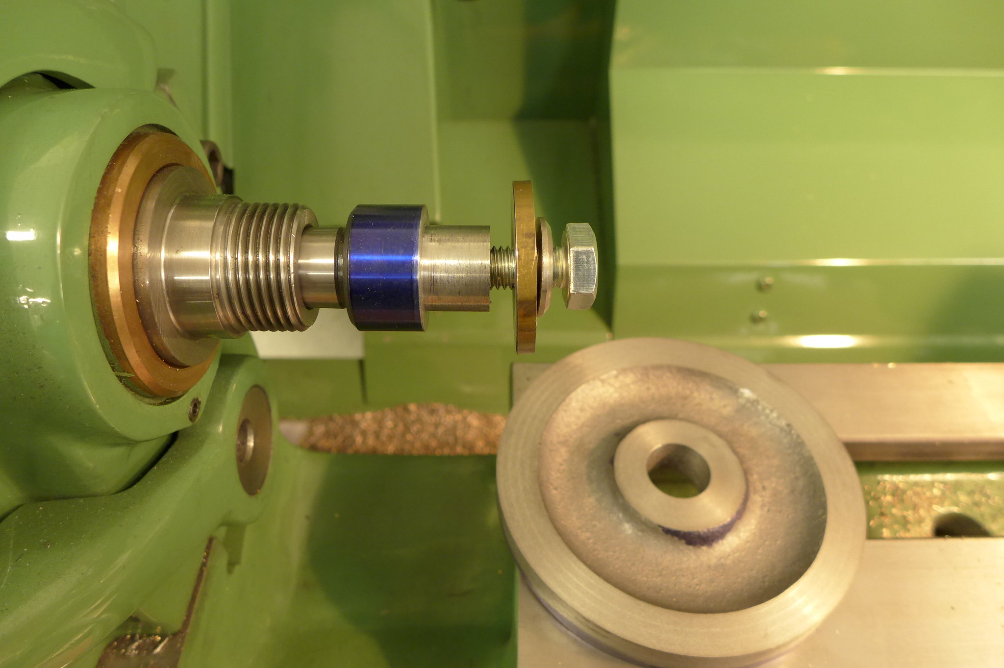 P1010142 P1010142 by Malcolm HARWOOD, on Flickr The wheels completed were now completed to final size. 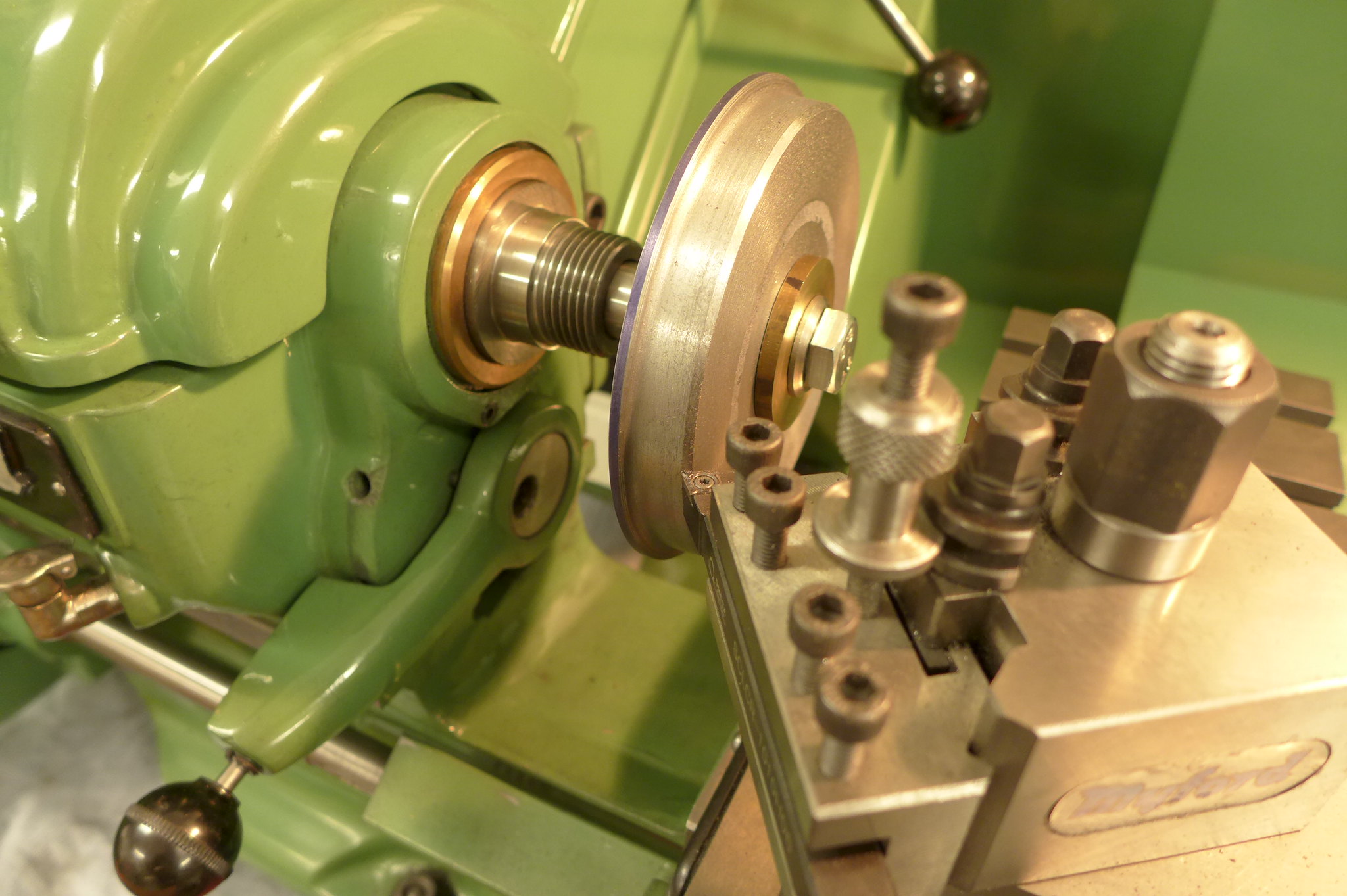 P1010143 P1010143 by Malcolm HARWOOD, on Flickr I then moved onto the fly cranks. Reeves had provided four PB castings but I struggled to hold them in the four jaw chuck as they were all slightly different in dimensions I was not confident I would find a good center for the 3/4" dia axle shaft and even more so the accuracy of the 7/16" dia crank pin hole the Don Young (DY) specifically said had to be 1.15625" from the axle shaft center line. As I had four to make I reasoned that the last thing I needed was four slightly different fly crank center lengths. I can't imagine that this is an aid to smooth running. DY suggests making them from MS and starting with 2x1/2' MS flat bar. This I did and had the parallel edges with which to mount it in the milling machine and accurately gauge the center line spacing with the help of the x axis DRO. As can be seen from the next picture I have invested in a rotary table, a Vertex H6. I hope to write a crit' of it in the tools section as it is not without its foibles. All in all though, a quality piece of kit. A plus point was that the bore of the H6 will accept a 2MT taper tool and so the wheel turning spindle doubles as a milling fixture as both wheel and crank have a 3/4" dia bore to locate upon. 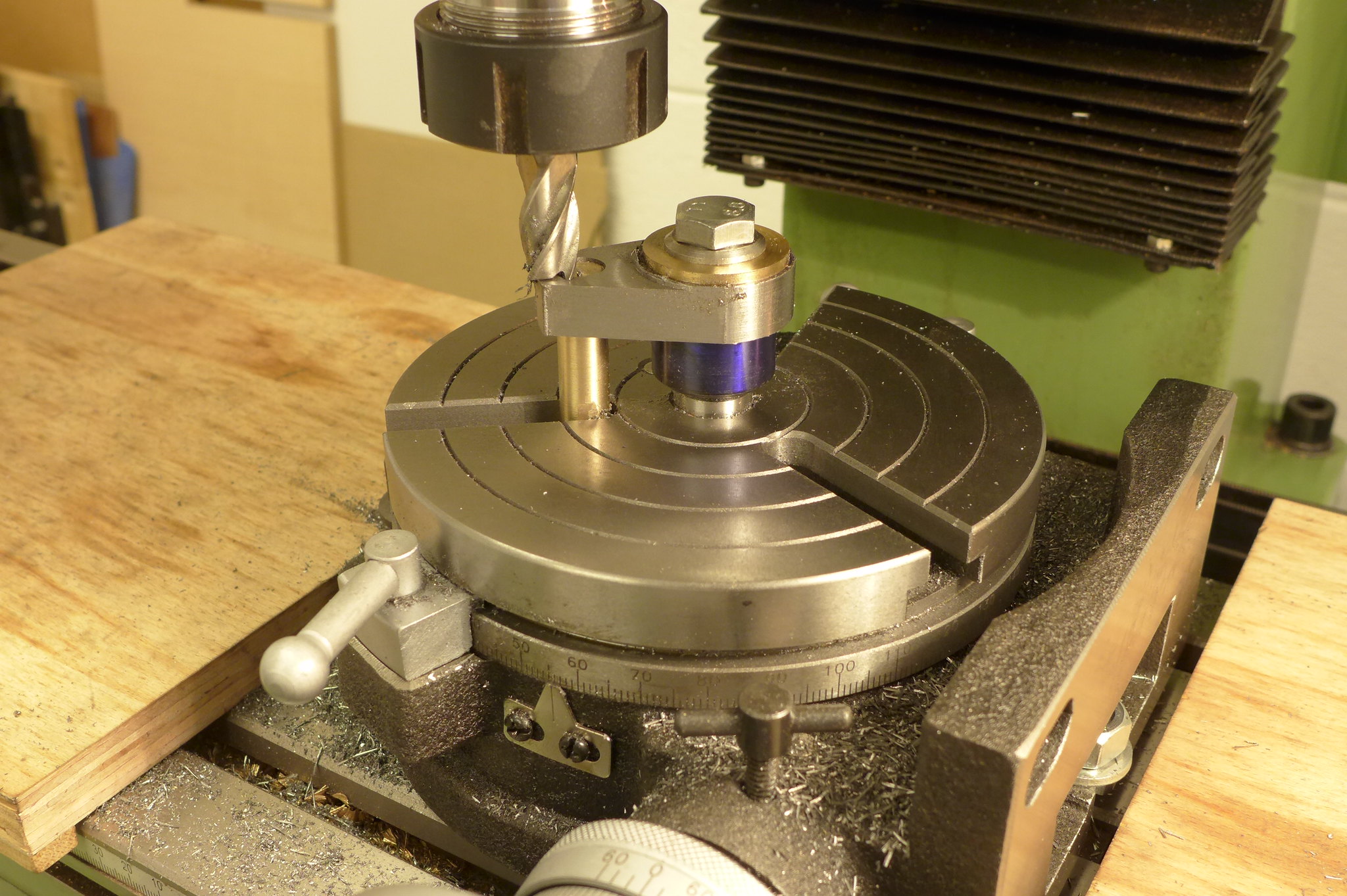 P1010144 P1010144 by Malcolm HARWOOD, on Flickr The large 1.375" dia "big end" was easy to do. The "little end" allowed me to reacquaint myself with the dangers of climb milling an unsupported work piece! However, one soon remembers and I turned up a small brass post that locates the 7/16" bore securely to the slot in the rotary table and away we went. The final 3/8" "little end" outer radius has to be completed by hand filing. Oh for one of those CNC mill thingies. 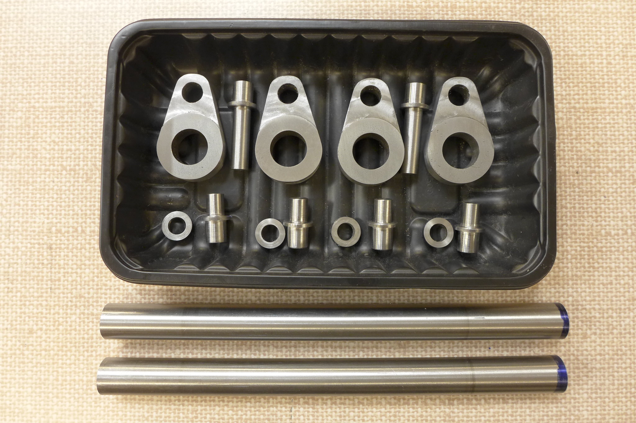 P1010146 P1010146 by Malcolm HARWOOD, on Flickr The crank pins and spacers are a relatively simple exercise in turning and are shown in the final picture of this update, complete with axle shaft, about to be faced, turned to length and centred to aid quartering. The high tech parts holder system is courtesy of a Sainsbury's Purple Sprouting Broccoli tray. P1010146 by Malcolm HARWOOD, on Flickr Next step is turning the eccentric sheaves. Should be interesting, parting off 2" dia MS bar! Thanks for reading. |
|
rrmrd66
Part of the e-furniture
Posts: 339
|
Post by rrmrd66 on Jul 25, 2017 19:21:40 GMT
Evening all Progress on two fronts to report. The axle blocks and keeps are finished. I bored the axle boxes on a face plate with an angle bracket, straps and counter weights. A bit Heath-Robinson but it works. The jaws on my 4 jaw chuck were not deep enough to hold a pair of axle boxes. 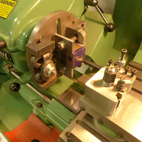 P1010127 P1010127 by Malcolm HARWOOD, on Flickr After milling the pocket for the spring push rod in the top of the axle block with a 1/2" dia bull nosed end mill I drilled the lubrication holes as per drawing. Those interested in these things will note the Dremel drill and stand. Hardly tool room kit, I hear you say. But very useful for doing the electrics in Senior Managements dolls houses and as long as you take it steady it is just about OK. By the way, a No 55 drill without negative rake on the cutting edge when breaking through brass doesn't half go ping. Anybody ken to make a new thread as per my last post on "tools in my toolbox that have not seen the light of day for 50 years"? Note the toolmakers vice, Never used. Worked perfectly with a bit of degreasing and derusting.  P1010128 P1010128 by Malcolm HARWOOD, on Flickr Here is one of the finished axle blocks with brass keep and felt pad /oil reservoir. 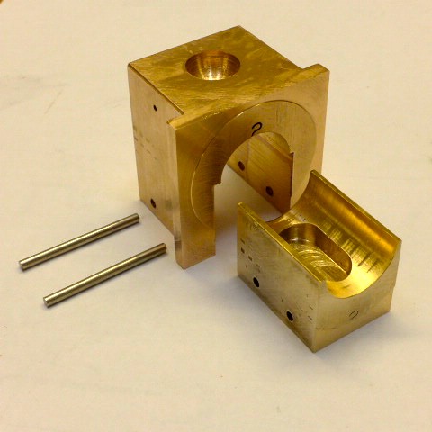 P1010129 P1010129 by Malcolm HARWOOD, on Flickr When I came to setting the side frame distance I did not have a vernier gauge large enough so I made a simple jig out of 2x1/4" plate. Bolted together and with 2x4mm end mill slots were just right to locate the side frames..  P1010124 P1010124 by Malcolm HARWOOD, on Flickr I couldn't resist just trying them out. 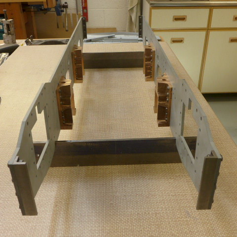 P1010125 P1010125 by Malcolm HARWOOD, on Flickr Here we have a full "dummy" set up. The objective here was to make sure that the axle shafts rotated in their axle blocks without undue binding. Fortunately they ran very smoothly. 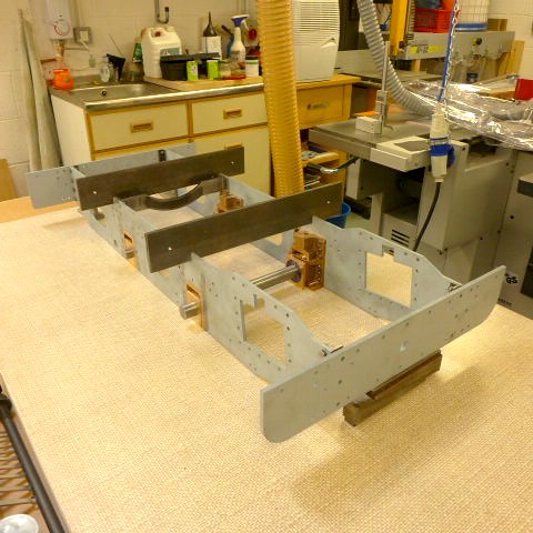 P1010130 P1010130 by Malcolm HARWOOD, on Flickr Finally here with the front beam all set up and bolted down I am spotting though to fix the drag beam to the side frames Note the setting gauge and the two set squares so that I know that the frames are the correct distance apart and the sides are vertical and parallel. The sharp eyed will notice my poor mans surface plate. A scrap piece of 10mm float glass, foc, from the local glass cutter.  P1010131 P1010131 by Malcolm HARWOOD, on Flickr Many thanks to Roger of Speedy fame for his tips on loading pictures from Flickr. I thought I had the hang of it last time but had forgotten how to do it. Grrr! Thanks for reading my ramblings Malcolm |
|
rrmrd66
Part of the e-furniture
Posts: 339
|
Post by rrmrd66 on Jul 13, 2017 18:44:27 GMT
Right! Let us hope that I have now solved the mystery of uploading pictures via Flickr, although I am still not too sure I will remember what I did in the end. I believe I left you on the last post with now blocked picture via Photobucket saying I would go and practice hand riveting, As you will see from the above post plus picture I did just that so I will not repeat the picture. After making sure that the rivets were flush with the frame sides ( I did as Roger did in his Speedy build and milled them to within a gnats whatsit of the frame side and tickled them up with a file). I was able to place them back to back on the mill and machine the two pairs of horn blocks as one. I hoped that this would result in perfectly matched and parallel sided horns. However a long series 5/8" end mill thought otherwise and even after taking three final "spring" cuts still managed to get a taper of about .005" per side. A bit of gentle filing though soon got the axle blocks fitting and running smoothly. 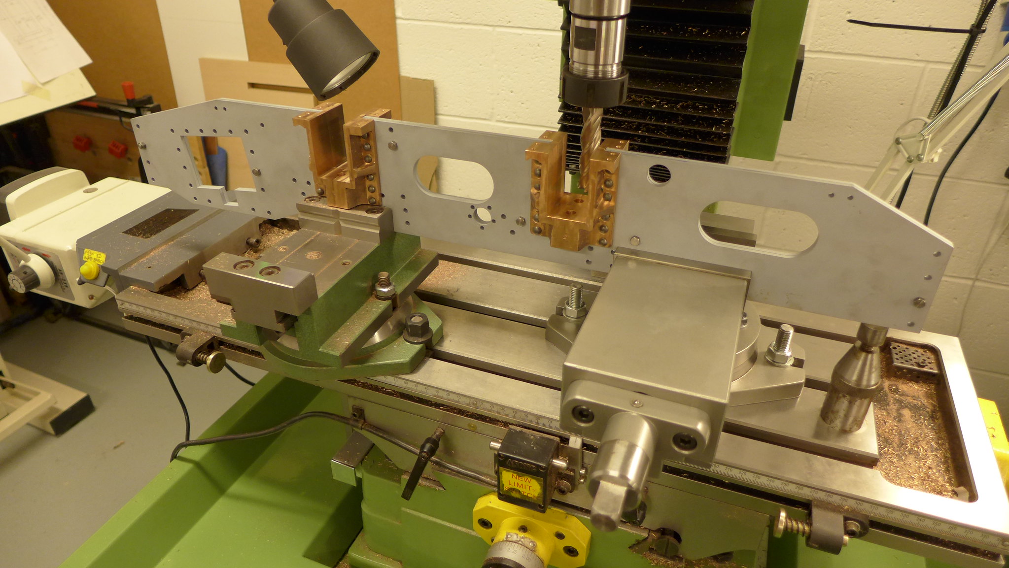 Side frames plus horns being milled together. Side frames plus horns being milled together. by Malcolm HARWOOD, on Flickr Note the two vices. One from Warco made in UK. Very nice but quite shallow jaws ( extra deep ones are an extra) and the other SOBA India via Axminster Tool ( I had a pile of gift vouchers from Christmas... so much more useful than socks). Quality OK and very solid. The observant will note the Toolmakers jack on the right hand side of the picture. I wonder how many tool making apprentices. like me, have had a unused set of these things lying in their toolboxes for 50 years? Maybe we should start a new thread on a "you show me yours and I will show you mine" basis? I am now half way through making the axle boxes with solid keeps and will report back shortly. Hopefully with pictures! I wonder when Flickr will catch on and start charging for 3rd party hosting? Thanks for reading Cheers Malcolm |
|
rrmrd66
Part of the e-furniture
Posts: 339
|
Post by rrmrd66 on Jul 13, 2017 18:16:43 GMT
Yahoo! I think I have it.
With apologies to Henry Higgins
I will try and continue the Hunslet build with this new found skill.
Thanks for tips guys.
Malcolm
|
|
rrmrd66
Part of the e-furniture
Posts: 339
|
Post by rrmrd66 on Jul 13, 2017 18:12:50 GMT
|
|
rrmrd66
Part of the e-furniture
Posts: 339
|
Post by rrmrd66 on Jul 13, 2017 15:29:53 GMT
Hi Mike
still doing something wrong I guess
I have pressed the "public " button but nothing seems to happen.
Malcolm
|
|
rrmrd66
Part of the e-furniture
Posts: 339
|
Post by rrmrd66 on Jul 13, 2017 15:27:38 GMT
|
|
rrmrd66
Part of the e-furniture
Posts: 339
|
Post by rrmrd66 on Jul 13, 2017 6:26:50 GMT
|
|
rrmrd66
Part of the e-furniture
Posts: 339
|
Post by rrmrd66 on Jul 10, 2017 17:17:53 GMT
Thanks guys
I have tried via the Roger method but can't seem to make the pic's "public" as per Rex's post.
Any one explain?
Cheers
Malcolm.
|
|
rrmrd66
Part of the e-furniture
Posts: 339
|
Post by rrmrd66 on Jul 10, 2017 12:10:46 GMT
|
|
rrmrd66
Part of the e-furniture
Posts: 339
|
Post by rrmrd66 on Jun 15, 2017 21:08:48 GMT
Here I give below my experience of purchasing the above.
20/1/17 Visit London Model Engineering show from North Yorkshire and place order with owner of Warco for Super Major Vario machine. ER32/R8 holder, wide tray and milling vice thrown in foc. Pay deposit. Agree March delivery.
21/2/17 Query why no order acknowledgement and receipt for deposit.
26/2/17 Ask for reply to above.
28/2/17 Agree to pay by direct debit in exchange for foc clamping kit. Confusion over foc vice. It is not the DH1 but a "Chinese' basic model. Agree to pay extra for DH1. Small discount agreed.
1/3/17 Amended invoice issued.
13/3/17 Machine delivered by local carrier. Notice later that packing case has hand written label which says Super Major Vario/DRO, but DRO is crossed out. Note machine manufactured in 2015. Send e mail stating no DRO
15/3/17 Chase up answer why no DRO as stated on invoice and paid for?
16/3/17 Offer received to a) come and collect the by now installed machine and fit DRO at works, or b) I fit DRO kit ( X and Y axis) myself and be given a 150 pound stg credit. I cannot agree with is and demand that Warco send an engineer to my workshop to fit DRO.
21/3 17 Chase up for a response.
24/3/17 Chase up for a response.
28/3/17 Informed after further chasing that engineer will visit . Date to be confirmed.
31/3/17 Chase again. Warco promise to get back with a date.
2/4/17 Still no date
5/4/17 I accept date offered of 24/4/17
24/4/17 Engineer arrives at 1800hrs and leaves at 2230hrs. Y axis fitted. X axis to be installed later in week.
28/4/17 Engineer fits X axis. All is now working.
3/5/17 ER32/R8 collet holder has no means of being held stationary whilst tightening the collet nut except by spanner on fixed nut on top of draw bar. This multiplies torque by x3.3. Spring pin in captive nut shears.
6/5/17 Warco send replacement draw bar but 7/16"UNF thread is not finished properly and will not screw into R8 holder. Order die from other supplier. Find out, when it arrives, it requires stock of 1 5/16" dia. which I do not have.
12/5/17 Milling head rise and fall motor power feed fails.
24/5/17 Engineer visits and finds reduction gearbox on rise/fall motor has failure on output shaft.
30/5/17 I notice on Warco web site a photo of ER32/R8 collet holder with two spanner flats. This will overcome problem when tightening up chuck. Ask Warco to exchange for this type. Warco say this is non standard. I obtain one from another supplier. Problem solved.
2/6/17 Replacement gearbox arrives. It looks like a pre-used one and there is no input gear.
5/6/17 New reduction gearbox arrives. I fit it. All is now working satisfactorily.
I should state that at all times, with the exception of one person, all members of Warco staff were courteous and helpful.
I leave it to you, the reader, to draw your own conclusions.
Thanks for reading
Cheers
rrmrd66
|
|
rrmrd66
Part of the e-furniture
Posts: 339
|
Post by rrmrd66 on Jun 15, 2017 20:03:28 GMT
The full size ones only have 4 holes for rivets each side I tried both just one is quicker!! Then I got married again?  It is a Hobby! Oh and you will find that the Hornstays are too wide if you look at the drawing the brake rods clash! I made new 5/16 square ones and put them in the outer holes!! They make nice packing pieces?? David and Lily. Hello Dave and Lily Thanks for the tip. Had a look at drawings and i think I can see what you mean Proceed with caution and leave the top on the Loctite for the time being in case of modification, eh? cheers Malcolm PS Lily. Sichuan King prawns are my favourite. |
|
rrmrd66
Part of the e-furniture
Posts: 339
|
Post by rrmrd66 on Jun 14, 2017 19:59:41 GMT
Evening all. The horn blocks are now all finished bar the final few thou to be removed when I have the two frames locked together a la Rogers WIKI on his Speedy construction.  fullsizeoutput_5eb fullsizeoutput_5eb by Malcolm HARWOOD, on Flickr Here they are above, complete with keeps, all number stamped as matched pairs to the frame. Because I have decided to rivet the horn blocks to the frames, as opposed to nut and bolt, I have in effect "spot faced" the holes with a 10mm dia end mill. This is to allow the 5/32" rivet snap to sit vertically to the side frame. After a few practice runs, on some scrap plate, I found that if the the plate being riveted was not held horizontal and the snap vertically, with little or no "fidgeting", then all was well. However if this was not the case then the snap OD started marking the plate and a small gap would appear under the rivet head. As can be seen I have had to cut into the webs on some, but I am sure there is enough thread engagement (with Loctite) to give me a good fixing. I have been reading Chis Vine's excellent book " How (not) to paint a locomotive". Should I undercoat as I go along or wait until the end and mask off? Maybe I should do a bit of both? However, I was trying to finish the frames and decided to grit blast them and apply a coat or two of acid etch primer . I have noted that on other threads this seams to be common practice. Fortunately I have an acquaintance with a grit blast cabinet and a big compressor. He kindly let me grit blast them for the price of a couple of pints. I countersunk the frame rivet holes on one side only to accommodate the swaged over rivet head. I then made a very rudimentary spray table in my empty garage and primed both frames and the front and ream beams.  fullsizeoutput_5ed fullsizeoutput_5ed by Malcolm HARWOOD, on Flickr Here they all are after two coats of U-pol no 8 acid etch. Easier than I feared. I can now start riveting the horn blocks to the frames. That will be in the next post. Thanks for reading Cheers Malcolm |
|
rrmrd66
Part of the e-furniture
Posts: 339
|
Post by rrmrd66 on Jun 3, 2017 16:37:09 GMT
Just got back from a drivers training day at Ryedale Society of Model Engineers at their East Gilling track.
Verdict. Brilliant.
It was my first time driving a 5" gauge loco.
Not much to learn though!
Just the signals. Oh and then there is injectors,left hand right hand, water from the tender off and on, when to and when not. The blower as well. Did I tell you about the regulators, each one slightly different on the three locos I drove. Then there is stoking the fire, taking on water and driving backwards at times and trying not to fall off I did twice whilst fidgeting when stationary (much to everybodies amusement and very easy if you are 6ft tall.)
However after the first 60 minutes of shear terror it does get easier.
If anybody else is thinking of having a go, my advice is do it.
Great Day. Great weather. Wonderful coffee cake.
Thanks Ryedale SME.
Must get my Hunslet finished ASAP.
|
|
rrmrd66
Part of the e-furniture
Posts: 339
|
Post by rrmrd66 on May 29, 2017 7:00:21 GMT
|
|
rrmrd66
Part of the e-furniture
Posts: 339
|
Post by rrmrd66 on May 28, 2017 20:29:09 GMT
Evening everybody
Don't know if the following is helpful, but here goes.
Foe many years my company was the exclusive UK distributor of a cast iron sealing ring used on tracked vehicles etc. (Known more commonly as a "Caterpillar" seal).
They were made of a very hard, yet flexible, cast iron by a the Goetze company (pronounced Gurtza) of Burscheid, Germany (now part of the Federal Mogul Corporation).
Their major product line however was piston rings supplied to all the major German car manufacturer. They also supplied marine diesel engine manufacturers. So, quite a range.
On my many visits to their foundries I was always fascinated by the amount of machining work that went into making one cast iron piston ring.
They were sand cast not round but "oval". All piston rings were cam turned "oval" and gapped to a shape that upon being compressed into the cylinder bore the gap would close to the required dimension and the piston ring would become round.
I recall something like an oil control ring went through something like 28 different turning and milling operations, normally held in a jig that gripped 20 or 30 rings, depending upon size.
Hope this was of interest
Cheers
Malcolm
|
|
rrmrd66
Part of the e-furniture
Posts: 339
|
Post by rrmrd66 on May 27, 2017 12:09:33 GMT
Looks sensible. Arc Euro do a collet nut with a ball bearing in it - which needs less effort to tighten (or goes tighter with the same effort): Arc EuroWilf Hi Wilf Yes I spotted that as well and have one fitted. It appears to work as suggested. Thanks for your interest Cheers Malcolm |
|
rrmrd66
Part of the e-furniture
Posts: 339
|
Post by rrmrd66 on May 27, 2017 9:51:53 GMT
Good morning everyone. Here is something I came across whilst getting use to my new milling machine (of which more anon when all issues with it have been satisfactorily sorted). The milling machine is a Super Major Vario. It was supplied with an R8 collet system. The problem arose when attempting to tighten the nut on the ER32 collet. The only way that I could find to apply an equal and opposite turning effort was the captive nut on the top of the draw bar. There is no spindle lock on this machine. (As a matter of interest do vertical milling machines have spindle locks any more? I am fairly certain that when I did my tool making apprenticeship, eons ago, it was possible to lock spindles on vertical millers. Maybe not?) The picture below shows the problem. 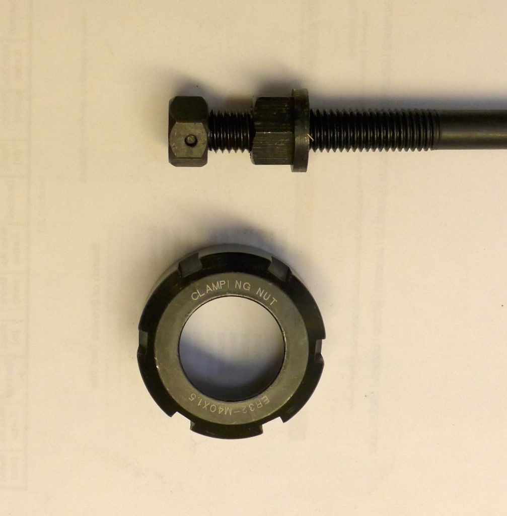 The collet nut thread measures approx 40mm dia and the draw bar nut about 12mm dia. This gives a torque multiplying factor of approx 3.33. The eagle eyed will not that the nut is held captive by a spring pin, about 1/8" dia and is made from chocolate. Following a scary episode where I managed to get a 1/2" end mill to start undoing itself when milling the sides of the horns on my Hunslet (see 5" gauge Hunslet thread build in General Chat) I tried to do extra tightening and sheared the pin. The milling machine supplier was very good and sent me a replacement by return. (The UNF thread at the other end was not right so a die and stock had to be obtained to run down the thread form to correct it, but that is another story.) So, what to do. After scratching my head and reading several threads I came up with the idea of a strap wrench applied to the only bit of surface on the tool holder that was available. Someone recommended milling two spanner flats on this portion as he had had a similar problem. I though that was a high risk strategy and looked for something less risky. The solution? A Boa (constrictor) strap wrench supplied by UK Tool Centre. It is very effective. The 1" wide rubber strap grips like whatsit and appears to allow safe milling once more. 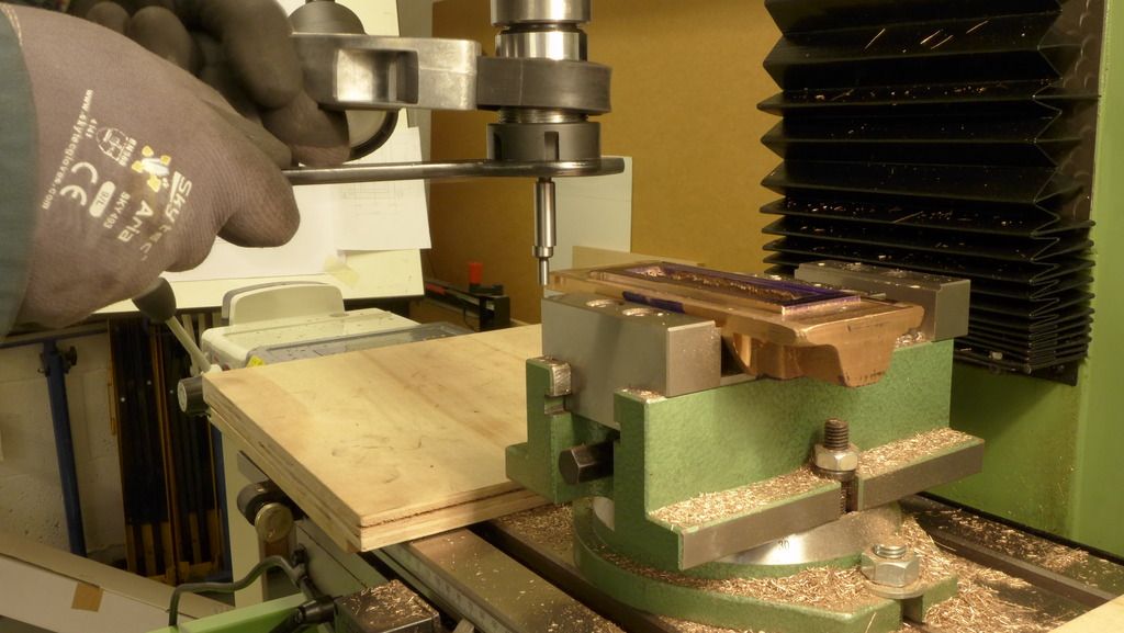 The picture shows me tightening a edge finder "wobbler", which obviously does not need to be super tight. However, for the purposes of illustration you get the idea. The chocolate pin has been replaced with a new one turned from silver steel and the nut has been permanently attached to the draw bar with a couple of tacks of weld. It should not come loose in the future should I revert to putting a spanner on it. Thanks for reading cheers Malcolm |
|