Evening all
Here is the latest update
Hydrostatic oil lubricator.
DY suggests that you make two mechanical ratchet type lubricator pumps and tanks, installed behind the front buffer beam. They looked quite complicated to me and I noted from "search" on the forum that the ratchets were not always long lived.
I had read about a pressurised lubrication system using steam condensate to force steam oil out of a tank and into the valve block in a back issue of ME.
I managed to obtain a single feed control valve with sight glass for SW Steam who assured me one was sufficient when used with a tee piece making sure that the feed pipes were exactly the same length to ensure even oil delivery.
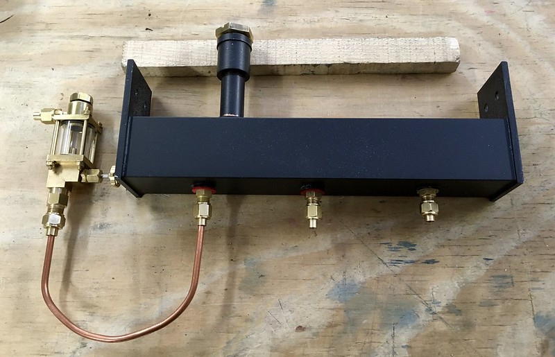
The photo shows the parts of the system. The tank is made for square section brass tube with let in silver soldered ends. It has an approximate capacity of 140cc. A supply union delivers condensate into the bottom of the tank at system pressure via a control valve from an additional tapping on the manifold. A weir type outlet takes oil forced up by the pressure of the condensate (oil floats on water) to the site glass where it can be regulated and on into the valve blocks. A water drain is situated in the middle of the tank, which is in fact now a cylinder drain cock valve (not shown). A more sophisticated operating lever is to be added shortly.
I was concerned that the control valve/sight glass may be a bit vulnerable to knocks in the position I had chosen on the running board. I though I remembered seeing the Hunslets at Porthmadog with "little dustbins" for the sand boxes. It was pointed rapidly by other forum embers this would have been a Fairlie not a Hunslet. Silly me!
I cut an observation window to check on the flow of oil going to the valves. The interior seemed very dark and a strip of Plasticard was installed to lighten the interior.
A filler tube with a 3/4" hex plug and O ring complete the assembly. This clearing the foot plate in front of the smoke box.
This shows the unit partially assembled. The cylinder drain cock is from SteamFittings of Barmouth. This thankfully has a generously proportioned actuating lever with a 6BA threaded hole, not the clock makers 10BA hole from other suppliers.
I sometimes wonder if our suppliers actually try using some of their products themselves in anger? They could not possibly be just chasing the lowest price from some wholesale supplier from the East (and I don’t mean Ipswich), could they?
As previously mentioned it is important if using a single sight glass lubricator and a tee piece to ensure that the two pipes downstream of the tee are of equal length. To guarantee this I made a simple soldering jig and used two pieces of pipe of exactly equal lengths.
This is the result after fitting. Fingers crossed that it will all work OK and pass a hydraulic test.
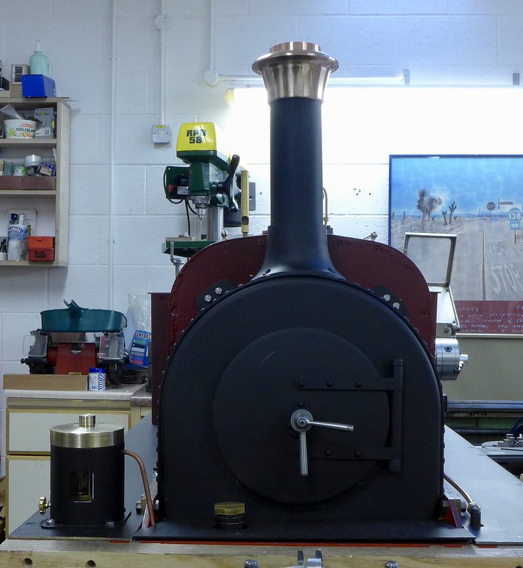
The engine from the front looks more or less finished. Although it is still mounted on the rotating stand. More on handling this extremely heavy engine (I guess 50+kgs) later on.
The completion of the piping up of the boiler backhead can now be completed
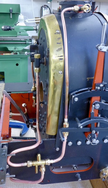
The backhead is now fitted with all its pipes and non-return valves. The emergency hand pump has been relocated into the space reserved for coal in the full size engine.
The left hand clack valve has a dual feed of either direct from the front axle crank driven boiler feed pump or when the bypass valve is shut via the emergency hand pump from the auxiliary water tank in the riding car. I had to do this as the ashpan operating damper lever was fouling the pump bracket. The red line sight glass work really well.
Note my take on asbestos rope lagging on the blower feed pipe. Where and how did I obtain that ? The newsagents. It's packing string!
The time had come to take the engine of its stand. I just hoped I was not going to regret it and find that I needed to sort something that was best reached with the engine on its back, upside-down.
The dumb buffers made from Sapele (I think) as per DY design had been lurking in the workshop for the last 4 years and at last I could fit them. I noted that on a visit to the Lake Bala Railway that the buffers has what looked like old boiler plate bolted to their faces. I did my best to replicate this with blued 10 thou' shim and 2mm self tappers. They are fixed to the buffer beams with 4mm dowel screws, which if ever you have self assembled IKEA furniture, you will know all about.
The right hand boiler feed clack is fed via a horizontal injector drawing water from the riding car tank and steam from the turret.
Note the damper operating lever for the ash pan. Also an extended cylinder drain cock operating lever. The original can be seen but there is virtually no room for fat fingers because of the brake pedestal.
The brake column is installed and connected to its arm under the running board.
I gave up trying to turn a hand beaten bead for the firebox trims. I think I need a bead roller (Jenny mill ?) but the purchase of specialty tools has to end somewhere.
The riding car is connected to the engine by a rigid coupling . The water is transferred by quick release couplings supplied by Polly Engineering. Dumb buffers awaitng fitting.
Next post will report on a solution to handling a heavy engine and first low pressure hydraulic tests.
Thanks for reading. We are almost there!
Cheers
Malcolm