|
|
Post by dhamblin on Dec 20, 2019 9:53:06 GMT
It wasn't a chance I was going to miss - favourite loco on home railway! Grandad and Dad would have been very jealous, but it's certainly given me added impetus to get the miniature version working again.
Regards,
Dan
|
|
|
|
Post by dhamblin on Dec 23, 2019 20:35:03 GMT
Boiler vacuum complete! 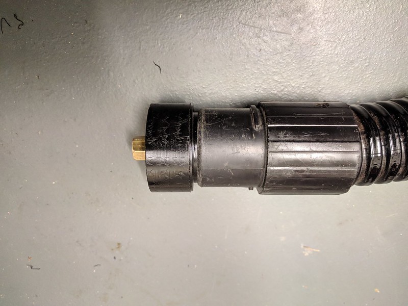 Test Fit Test Fit by Daniel Hamblin, on Flickr I made an adapter out of nylon, with a 1 degree taper to match that on the vacuum cleaner nozzle. Seen here having a successful test fit. 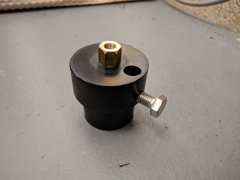 Vacuum Nozzle Adapter Vacuum Nozzle Adapter by Daniel Hamblin, on Flickr The completed adapter. The brass insert is threaded 5/16 x 32tpi ME to match the same fitting used to attach the boiler to the CSME test kit. A M8 hex head screw is used to provide a bypass vent. I intend to use this adapter in future with a long tube nozzle screwed onto the brass fitting to access all the awkward areas that need ash and clinker removing after a running session.  Firebox Backhead Support Firebox Backhead Support by Daniel Hamblin, on Flickr The boiler needs to be placed vertical so the stay nuts that require sealing are horizontal. The cut outs and holes are to accommodate the backhead fittings and mounting studs and allow as much surface contact area as possible.  Boiler Vacuum Set-up Boiler Vacuum Set-up by Daniel Hamblin, on Flickr Vacuum cleaner connected up to allow the Loctite 648 to be wicked into the tiny gaps on the two leaking firebox stays. After applying some around the stay nuts the vacuum cleaner was started and with a little bit of leak plugging on the nozzle itself I left it running until the motor cut out. The boiler has now been left overnight for the Loctite to cure. EDIT: I forgot to mention; my thanks to David (Midland) for the use of his bottle of Loctite. That's it now on the boiler until the 2x hydraulic test, with any luck it will pass this time but I'm taking nothing for granted. In the meantime I will be concentrating on the wheelsets, with the first job being a check of the driving wheel quartering. If that looks in order I will be pinning the axles and wheels using taper pins before putting a chamfer and radius tip on the flanges. This will need the wheelsets to be set up between centres on the lathe. Happy Christmas to all!  Regards, Dan |
|
|
|
Post by dhamblin on Jan 7, 2020 18:21:25 GMT
Summary of the Christmas and New Year period work:  Wheelset Pin Wheelset Pin by Daniel Hamblin, on Flickr Once I'd cleaned all the grime off I was pleasantly surprised to find each driving wheel had been pinned to the axle to preserve the quartering. Each pin head has been filed to match the wheel casting profile, so they weren't easy to spot, fortunately there was a second empty hole on one of the leading driving wheels that gave it away.  Chassis Cleaning Chassis Cleaning by Daniel Hamblin, on Flickr The chassis is starting to look a lot better, although some touch up paint will be required as no primer was used when it was originally painted.  Cleaned Wheelsets Cleaned Wheelsets by Daniel Hamblin, on Flickr All the driving wheelsets have now been removed and cleaned. Both eccentrics (axle pump and lubricator) don't appear to be truly square to the axles, the axle pump one also not being properly in line with the pump bore, so much so that the wheelset moves laterally by up to 5mm at a certain point on each revolution. Pressing the eccentric further along the axle should cure this.  Bogie Dismantled Bogie Dismantled by Daniel Hamblin, on Flickr Leading bogie has been dismantled to free both wheelsets, which will be the first ones to be re-profiled. The intention is to hold one end in the independent four jaw chuck, secure both axleboxes to that end using cable ties, then support the other end using a fixed steady. A centre can then be drilled in the free end, the whole thing reversed and repeated, thus allowing the wheels to be turned between centres to get the flanges re-profiled.  Boiler Test No. 2 Boiler Test No. 2 by Daniel Hamblin, on Flickr Now we come to today: second attempt at the 2x hydraulic "shell" test, seen here during the 160psi holding phase. I am happy to report that it passed and boiler W009806 is now officially recognised. I will engrave the number on the backhead over the coming days. Once the wheelsets are completed it will be on with making the new backhead fittings and preparations for the 1.5x hydraulic test, which will add the superheaters to the mix as well. Best start getting the shopping list ready for Ally Pally  Regards, Dan |
|
JonL
Elder Statesman
   WWSME (Wiltshire)
Posts: 2,990
|
Post by JonL on Jan 8, 2020 22:37:10 GMT
Superb!
|
|
|
|
Post by dhamblin on Jul 4, 2020 21:22:21 GMT
Time for an update on progress since January. 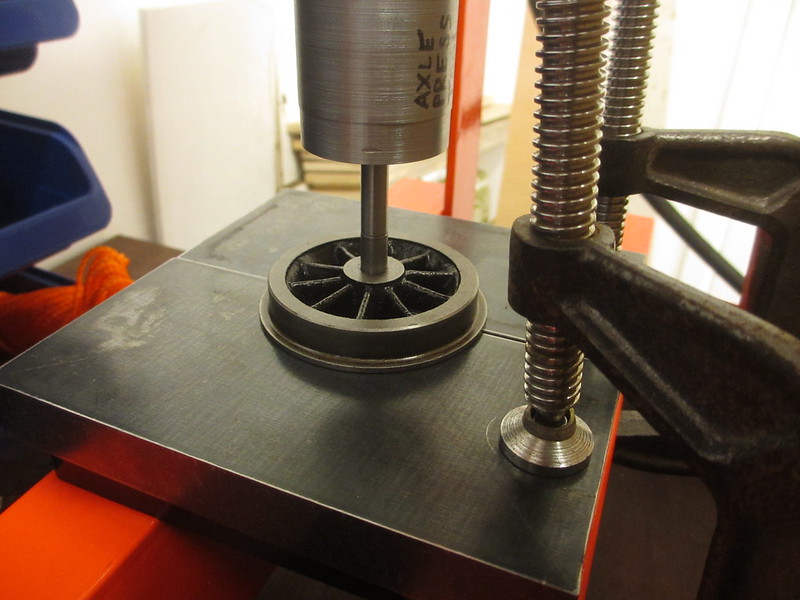 Wheel Press 1 Wheel Press 1 by Daniel Hamblin, on Flickr The wheelsets have been the main focus since the boiler passed the shell test. My plan was to try and improve the wheel profiles to better match the SMEE profiles (see first page of this thread), by machining them with the wheelset rotated between centres. An initial attempt at adding centres to the bogie and pony truck axles was unsuccessful as I learnt the hard way how difficult it is to centre something like a whole wheelset in a 4-jaw chuck and expect the free end to be centred too! So, buy a hyraulic press, machine a press tool out of some EN3B, sort out some suitable press plates from 20mm thick steel and the wheels come off. Please excuse the finish on the tool, it wasn't the nicest material to machine.  Wheel Press 2 Wheel Press 2 by Daniel Hamblin, on Flickr Getting the DRO sorted on the lathe before lockdown started was a massive boost and the first part of the enforced work from home focused on using it to machine the replacement axles from 5/8" silver steel. Here the axles press tool is being used with a third 20mm thick steel plate to reassemble the first bogie wheelset.  Tender Wheelsets Tender Wheelsets by Daniel Hamblin, on Flickr All three tender wheelsets were dismantled and centres drilled in the axle ends using the collet chuck. Unfortunately this showed that they must have originally been machined in a slightly out 3-jaw self-centring chuck as the run out was up to 6-thou. Today I have just completed the third replacement axle. 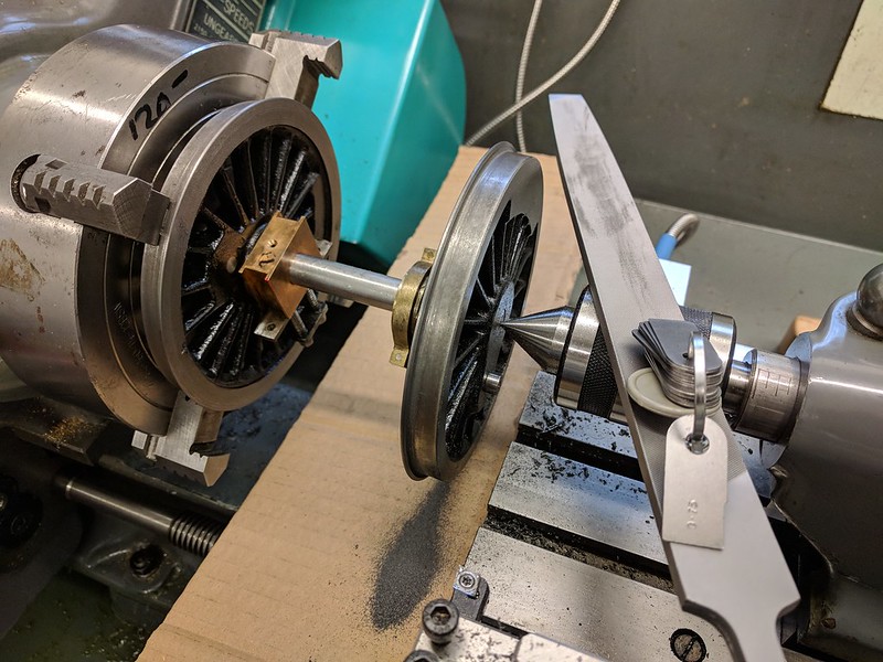 Leading Driving Wheelset Leading Driving Wheelset by Daniel Hamblin, on Flickr Lost all of April as I slit my finger open trying to get a new milling cutter out of a tight hole in its wooden packing block, so on to May. Run out on the driving wheelsets was even worse - the leading driver here was out by 0.01"! To try and get the treads in roughly the right place for sorting out the square tip flanges I resorted to manually adjusting the shallow axle centres using an automatic centre punch and carefully applied pressure to move it to a point where the run out was about 0.003" or better. This was successful and, with the wheelet between centres and the 4-jaw chuck used to grip one wheel for turning, it was possible to manually file the flange profile using a smooth cut file and radius gauges for the flange tip. The 20 degree chamfer angle being done by eye as "best endeavours". As there is also a small amount of axial wobble the 2 degree cone angle has been omitted from the driving wheelsets.  Re-profiled Driving Wheelsets Re-profiled Driving Wheelsets by Daniel Hamblin, on Flickr Flanges modified on all three driving wheelsets. Only need to adjust the axle pump eccentric position (centre driver, seen here on the left) and repaint then these will be ready for chassis reassembly.  Bogie Wheel Machining Bogie Wheel Machining by Daniel Hamblin, on Flickr First bogie wheel having the 2 degree cone angle added to the tread. Initially machining is done using a right-handed 95° turning tool, with the DRO used to set the flange root as the datum point, then hand crank the lathe to slowly take the bulk of the material off (using the compound slide set over to 2 degrees). The tool pictured is then set to lightly kiss the newly machined tread and taken across to blend into the dead zone of the flange root from the original LBSC parallel tread profile. 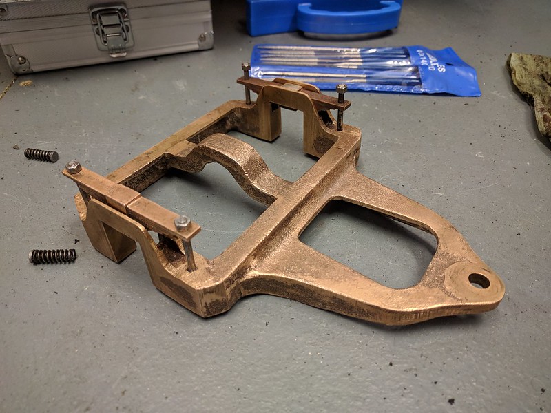 Pony Truck Pony Truck by Daniel Hamblin, on Flickr With all the wheelsets done and working days extended due to additional COVID-19 planning tasks coming in I needed something simple to fill the time in. I had hoped to simply touch up the paintwork but given the lack of primer it would only come of quickly again, so have made a start on taking it all back to bare metal. Here the pony truck has been stripped. 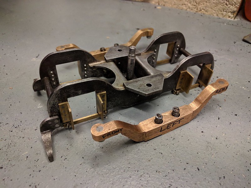 Bogie Bogie by Daniel Hamblin, on Flickr Bogie stripped of paint. Everything is getting labelled up due to the long gaps between getting worked on I need to make sure orientation of components is not lost. Over the next week I'll be re-machining the tender wheelset profiles then on to stripping the tender itself of paint. My aim is to get everything ready for a single session of applying primer before moving on to painting the chassis so it can be reassembled. Then it will be on to new backhead fittings and prepping the boiler for 1.5x hydraulic test. I've mentioned previously that I work in rolling stock engineering with London Underground, well the job I am currently on was one of the ones that has been kept going as part of essential maintenance. An interesting quirk of working from home is the tendency to work longer hours as you're 'logged in' to the company IT system, which means it is very easy to lose evening workshop time mid-week compared with trying to stick to rigid office hours. We've been told that the earliest date for returning to our office in Southwark is October, but more likely January 2021 or possibly later. Interesting times... Regards, Dan |
|
|
|
Post by dhamblin on Sept 17, 2020 21:13:07 GMT
A little teaser of what is to follow Britannia through the workshop:  New Wagons New Wagons by Daniel Hamblin, on Flickr I saw these four 3 1/2" gauge wagons on SRS and couldn't resist. The running gears will need some work and the coal wagon in particular will need new axles as the back-to-back dimension is large to gauge (may require surgery on the chassis as the wheels are right up against the axleboxes). My thinking is to use the experience gained to create some wagon designs of my own, including a suitable brake van. On Britannia - the lathe seems to be behaving itself now with the new motor and VFD, so one more tender wheelset to go and on to the backhead fittings. Regards, Dan |
|
|
|
Post by dhamblin on Nov 29, 2020 21:03:30 GMT
Little bit of an update:  Tender wheelsets Tender wheelsets by Daniel Hamblin, on Flickr All wheels have now been re-profiled - the last tender wheelset was part way through being machined when the pulley key on my lathe motor came loose and struck the guard. Had to wait for a motor upgrade and a load of summer renovation jobs to be completed before I could return to it. 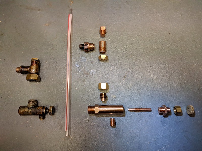 Gauge glass components Gauge glass components by Daniel Hamblin, on Flickr Now on to the serious stuff - all the components machined for the new upper and lower gauge glass fittings. Just need to drill the cross holes and silver solder it all together. The handle is a transition fit on the spindle and will be held in place with a taper pin, which will also serve as a lever.  Valve spindle Valve spindle by Daniel Hamblin, on Flickr Tool set-up used to machine the spindle taper. Bear in mind I don't have a great deal of formal training, this was reached with a bit of trial and error.  Brake isolation valve Brake isolation valve by Daniel Hamblin, on Flickr New brake isolation valve components and the original at the top. Still need to machine a hex on the valve body, but that will have to wait until the lathe is put into milling / drilling mode.  Injector steam valve Injector steam valve by Daniel Hamblin, on Flickr New injector steam valve components. The body can be re-used as it does not screw into the boiler. Just waiting on a 5/32" x 40 ME set of taps and dies to match the valve spindle thread in the blower valve, as I have a cunning plan to re-use it and achieve a captive valve spindle. Although the body for it is brass, it is screwed into a blind bush on the backhead and takes its steam supply from the turret, so I do not need to replace it with a bronze version. This is in keeping with my philosophy to use as much of Grandad's original material as possible. Regards, Dan |
|
JonL
Elder Statesman
   WWSME (Wiltshire)
Posts: 2,990
|
Post by JonL on Dec 1, 2020 15:41:56 GMT
Fantastic work.
|
|
|
|
Post by dhamblin on Jan 4, 2021 22:54:55 GMT
Back at work today (all of a metre commute these days...) after Christmas break, so a good time to update on progress. 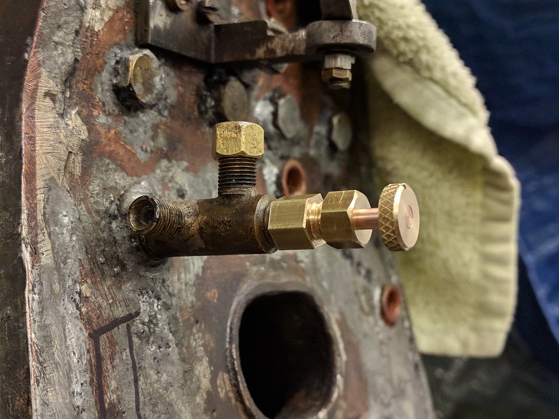 Blower Valve Blower Valve by Daniel Hamblin, on Flickr The cunning plan to re-use the blower valve body - new spindle held in place by an additional cap piece, with new gland nut on top. Trial assembly showed all items fitting well.  Hand Pump Backhead Feed Clack Hand Pump Backhead Feed Clack by Daniel Hamblin, on Flickr Replacement hand pump backhead feed clack components machined. I did make a new cap after this photo was taken, to account for the side hole and to correct the ball lift to the specified 1/32". 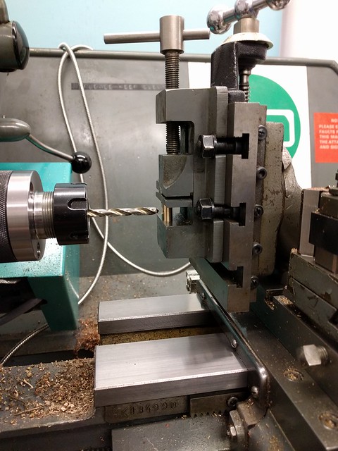 Cross Drilling Cross Drilling by Daniel Hamblin, on Flickr Brass test version of the clack body being used to check fits and accuracy of cross drilling in the lathe. Rather than make an error with the new bronze components I figured it was better to try this out on some brass, which turned out to be a good idea as it allowed the spigot to be turned down to get a better overlap with the hole drilled in the body.  Gauge Glass Mock Up 1 Gauge Glass Mock Up 1 by Daniel Hamblin, on Flickr Trial fit of the new upper and lower gauge fittings to see how bad the bush misalignment is. From the 'What's New' thread this also shows position of the longitudinal stay nut w.r.t. the lower fitting and how the lower gland nut for the glass needs to be made a bit longer to ensure the firebox crown is still covered in water when the level visible in the glass is right at the bottom. A new gland nut will be made so its top sits level with the longitudinal stay centre line. The flat register for the glass 'cup' on the lower fitting will be done once the top fitting has been silver soldered together so as to ensure correct alignment because:  Gauge Glass Mock Up 2 Gauge Glass Mock Up 2 by Daniel Hamblin, on Flickr Poor alignment of upper and lower gauge glass bushes, which needs to be accounted for when all the items are silver soldered together and assembled. 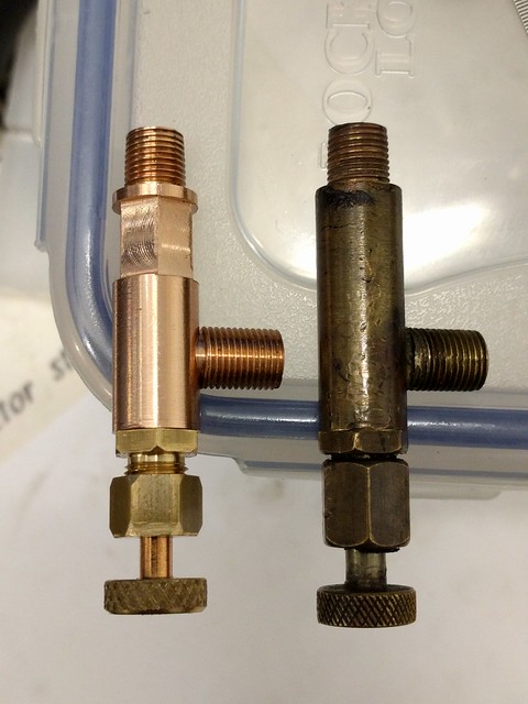 Brake Isolation Valves Brake Isolation Valves by Daniel Hamblin, on Flickr New brake isolation valve (on left) and original. The new valve has had a hex added to the body to make it easier to screw into the bush, which was the first time I had used the lathe to do milling. This still needs the threaded spigot to be silver soldered to the main body.  Test Kit Adapter Test Kit Adapter by Daniel Hamblin, on Flickr New boiler test kit adapter made to fit the safety valve bush, as the existing one needs to be removed from the turret bush to permit reassembly of pipework for 1.5x hydraulic test.  Pipework Assembly Pipework Assembly by Daniel Hamblin, on Flickr To finish off the holiday I managed to assemble the turret, pipe and blower valve together. The blower valve handwheel has been secured to the spindle using a 1/64" taper pin, which provides a convenient handle as well. The injector steam valve was assembled tonight and I need to get some gloves etc. to have a go at silver soldering next weekend. Regards, Dan |
|
|
|
Post by dhamblin on Jan 10, 2021 20:13:00 GMT
Quick update prompted by some good progress today.  Live Steam Injector Valve Live Steam Injector Valve by Daniel Hamblin, on Flickr Live steam injector valve assembled. Handwheel secured to spindle using taper pin and O-ring secured inside gland nut. Stag A jointing paste used to seal threads. This will be connected to its pipe and onto the firebox turret near to the test as it hangs in free air without the second pipe to the injector. 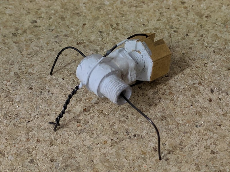 Silver Soldering 1 Silver Soldering 1 by Daniel Hamblin, on Flickr The hand pump backhead feed clack prepped to have the body and spigot silver soldered together. A ring of 1mm dia. 455 silver solder has been formed around the joint and then smothered in HT5 flux. Tipp-Ex has been used to cover surfaces where I don't want the flux and hence the silver solder to flow on. A brass end cap has been machined to hold the florists wire used to secure the two parts together. A further piece of wire passes through the body to prevent it turning over.  Silver Soldering 2 Silver Soldering 2 by Daniel Hamblin, on Flickr Assembly after heating with the propane/butane mix gas torch. Flux has flowed well and so has the silver solder by the look of things.  Silver Soldering 3 Silver Soldering 3 by Daniel Hamblin, on Flickr Hand pump backhead feed clack body after cleaning (20 minutes immersed in citric acid in the ultrasonic cleaner at 55 deg C). Silver solder has fully penetrated the joint - very pleased with that at a first attempt. I'll sort out the other fittings that need silver soldering together and then post an update when they've all been installed on the backhead. Regards, Dan |
|
|
|
Post by Deleted on Jan 10, 2021 21:05:50 GMT
Great work Dan...
Pete
|
|
|
|
Post by dhamblin on Jan 24, 2021 22:08:28 GMT
Backhead Complete   Top of Backhead Top of Backhead by Daniel Hamblin, on Flickr Upper gauge glass fitting and brake isolation valve silver soldered together. The latter (on the right) has been fully assembled with handwheel pinned and O-ring on the spindle. The upper gauge glass fitting required some fettling as the silver solder flowed onto the gland nut thread. This required further metal removal to fit the die to clean up the thread.  Milling Milling by Daniel Hamblin, on Flickr Milling a flat on the lower gauge glass body for the gauge glass cup. Vertical slide is tilted over 1 degree to match the angle between fitting and glass tube passed through the upper fitting. While everything was correctly set-up the 4.8mm hole was drilled for the cup to sit in.  Lower Gauge Glass Fitting Lower Gauge Glass Fitting by Daniel Hamblin, on Flickr Lower gauge glass fitting immediately after silver soldering on the blowdown pipe spigot and gauge glass cup.  Lower Gauge Glass Fitting Lower Gauge Glass Fitting by Daniel Hamblin, on Flickr After cleaning in the ultrasonic tank (and a bit of wet and dry to shine the surface again) the body was trial fitted in the backhead bush. Fully penetrated silver solder joints and good alignment. That trick of putting a ring of silver solder around the joint definitely works.  Gauge Glass Fitting Gauge Glass Fitting by Daniel Hamblin, on Flickr The gauge glass was cut to length using the lathe, on slowest speed, and a Stanley knife blade. The ends were heated to clean up the cut. A new, longer, gland nut was made for the lower fitting to make sure there is always a decent level of water covering the firebox crown when it is at the bottom of the glass. The whole assembly, including blowdown valve, was then erected on the backhead with O-rings to seal the glass.  Completed Backhead Completed Backhead by Daniel Hamblin, on Flickr The backhead fully assembled with pressure gauge and syphon, plus the live steam injector valve on the right. This and the pressure gauge will be removed to prevent damage until the 1.5x hydraulic test can be carried out. The hand pump backhead feed clack has also had a sacrificial stainless steel ball crushed on the seat (made a silver steel tool to do that in the bench vice) and then assembled with a new ball. Pressure gauge has had a red line painted on the dial at working pressure of 80psi. The top rght corner is a bit busy but looking at all the old photos from 1993 and 2005 it should all fit inside the cab structure. I have some 6BA bronze countersunk screws to make for the dome cover to replace a couple of stripped brass ones. Then some proper 10BA bronze screws for the feed clacks and fittings to allow pressure testing of the superheater assembly. Incidentally, the pressure gauge is missing one of its three brass dome head screws that hold the face cover on: 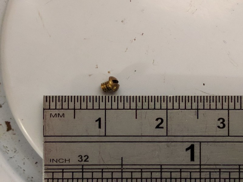 Pressure Gauge Screw Pressure Gauge Screw by Daniel Hamblin, on Flickr Any ideas what the thread type is and whether they can be purchased anywhere? Any help gratefully appreciated. Regards, Dan |
|
|
|
Post by andrewtoplis on Jan 25, 2021 20:55:44 GMT
Dan, your post upthread mentions brake isolation valves, does your loco have a steam brake on it?
|
|
|
|
Post by dhamblin on Jan 25, 2021 21:50:33 GMT
Dan, your post upthread mentions brake isolation valves, does your loco have a steam brake on it? It does have a steam brake, much simplified and uses the vacuum brake pedestal control. The pipe to the cylinder was cut at some point so I presume it was not a great feature to have and most of the opinions suggest brake effort is all or nothing in 3 1/2" gauge. I'll pipe the pedestal up but leave it disconnected from the cylinder for now. Regards, Dan |
|
JonL
Elder Statesman
   WWSME (Wiltshire)
Posts: 2,990
|
Post by JonL on Jan 25, 2021 22:19:19 GMT
Your soldering looks grand there. This is really coming together.
|
|
|
|
Post by dhamblin on Jan 26, 2021 9:59:15 GMT
Your soldering looks grand there. This is really coming together. Thanks Jon, must admit I was worried about doing it as I struggle to do electrical connection soldering for the r/c car (battery wires on to Dean's connectors and melted plastic!). But having read Keith Hale's book from CuP Alloys it made things considerably easier. Suspect I could have used smaller diameter rod but that is a minor improvement. I very much want to make as much progress on boiler and chassis as possible during lockdown 3. This is driving investment decisions e.g. blasting cabinet and compressor. That way, when restrictions allow, I can get the 1.5x hydraulic done and move swiftly into reassembly for steam test (assuming a pass). Even if that's a fail at the first attempt I want to be ready to quickly put fixes in place. The locomotive will be 60 years old next year - got to be worth celebrating in steam. Regards, Dan |
|
|
|
Post by keith1500 on Jan 26, 2021 12:18:24 GMT
I agree the silver soldering looks very neat.
You shouldn’t struggle with electrical soldering.a good iron and the right tip are a good start. I find a lot of our current apprentices struggle with soldering and it comes down to “great expectations” they expect too much from the solder, they expect it to flow on its own. The problem is often using old solder where the flux has become less effective.
.
Try applying a little flux on the end of the wire that’s already been tinned. Then it should flow nicely on to joint. Spikes and other solder issues are often down to lack of flux and the solder no longer wanting to flow.
Good luck
Keith
|
|
stevep
Elder Statesman
  
Posts: 1,073
|
Post by stevep on Jan 26, 2021 17:34:54 GMT
Also, if a soldering iron is held against a joint or a wire, the solder won't melt because the iron is only touching a small part of the joint. Melting some solder on to the tip of the iron establishes a thermal link to the joint, and everything them melts rapidly
|
|
|
|
Post by dhamblin on Jan 26, 2021 21:23:26 GMT
Thanks Keith and Steve - all tips logged away for future reference. Yet to crash the car badly enough to break any electrical connections but some new batteries might get purchased for when racing resumes (when the restrictions allow).
Regards,
Dan
|
|
|
|
Post by dhamblin on Mar 2, 2021 21:52:01 GMT
Added a further capability to the lathe, superheater assembly ready for 1.5x hydraulic test and I need to tap into the membership's combined wisdom regarding grate and ashpan design.  Rotary Table Rotary Table by Daniel Hamblin, on Flickr I bought this rotary table last year but only got around to testing it out now as I needed to hold a brass disc to drill four holes in it. Needed to get some M6 cap head screws to use with the T nuts that fit the rotary table body.  Superheater Assembly Superheater Assembly by Daniel Hamblin, on Flickr Superheater assembly ready for 1.5x hydraulic test. A new adapter fitting for the CSME test kit was made for the wet header and secured with 6BA screws. Two plugs were also made for the cylinder steam pipe ends. The baked on soot was cleaned / scraped off so the solder joints and underlying metal condition can be inspected. Also made ten 10BA bronze cheese head screws for the boiler top feed fittings and a further eight 10BA cheese head bolts for the blowdown valve. The valve is next on the list for modification, with an O-ring replacing the hallite packing. I'm starting to think ahead to rebuilding the grate and ashpan assembly. The current one has seen better days but I think the ashpan can be recovered and modified to make it easier to clean out. I've been referring to Steve's thread regarding the design of removable firebars.  Firegrate Firegrate by Daniel Hamblin, on Flickr The LBSC design uses nineteen steel bars 4 1/4" long, 3/8" deep and 1/8" thick. Two sets of six on each side and seven in the middle drop section. Clearly Grandad modified this to be six on each set and it does fit the firebox nicely.  Pony Truck Pony Truck by Daniel Hamblin, on Flickr Unlike the real locomotive LBSC didn't design the ashpan to straddle the rear frames, instead ash is intended to fall into the centre section. When I removed the boiler it was clear the two side shelves were clogged with ash and clinker right up to the bars and the material in the centre section was difficult to remove too.  Ashpan Ashpan by Daniel Hamblin, on Flickr With the pony truck removed it makes accessing the ashpan considerably easier, making me think this is the best solution for cleaning the fire out when back in the workshop. The idea would be to put a hinged door in the centre section of the ashpan and a smaller hinged door on the forward part of each side section. The centre section door would allow enough room for removing the three grate sections. The two outer grate sections would be modified to sit on the existing vertical brackets (two each side). The centre section, rather than hinging on a single shared rod with the outer two, would rest on pins attached to the two outer sections. The centre section could still be made to drop in an emergency by extending two of the bars so they sit under the cab edge of the foundation ring, then inserting a pin through them across the whole width of the ashpan. There is clearly a benefit in having tapered firebars so this could be done by milling each one on an angle plate on the vertical slide. Where there are connections to other firebars the tapered section can be sculpted back to rectangular using a ball nose endmill. Hope that makes sense without drawing it all out! It would be great to get some feedback on whether this will work or if there are potentially better ways of doing it. I have made a conscious effort to retain the existing ashpan, part of the overall philosophy of retaining as much as possible from original build. Regards, Dan |
|