|
|
Post by Jim on Jan 28, 2023 23:16:04 GMT
You're doing a lovely restoration job Dan.
Jim
|
|
|
|
Post by dhamblin on Jan 29, 2023 20:25:14 GMT
Thanks Jim, fortunately Grandad gave me a very good base to work on. I've also learnt so much on here, including from yourself.  Locking Plates Locking Plates by Daniel Hamblin, on Flickr Today's work: 3mm thick brass plate with hole sized to the chimney diameter then cut in half. The existing smokebox mounting holes were then used to mark the positions for drilled and tapped 8BA holes, with the angle done by eye.  Petticoat Pipe Installed Petticoat Pipe Installed by Daniel Hamblin, on Flickr Petticoat pipe installed in the smokebox, with the plates cut in half again to get better alignment with the smokebox mounting holes and also to allow adjustment of the petticoat angle.  Chimney Chimney by Daniel Hamblin, on Flickr Calculations were pretty good and the top of the petticoat pipe is a very close match for the chimney top. The 8BA countersunk screws will be painted satin black in due course. If I was starting from scratch the screws would be hidden under the chimney.  Front End Front End by Daniel Hamblin, on Flickr Front end of the engine looking ever more complete now the chimney is fitted. Regards, Dan |
|
|
|
Post by dhamblin on Mar 5, 2023 22:20:09 GMT
Closer to the finish Primer Application Primer Application by Daniel Hamblin, on Flickr Smokebox number and shedcode plates plus spacer and the reverser assembly after spraying in etch primer. I'd like to say these are the last bits that need primer applying, but I've probably missed something!  Smokebox Plates Smokebox Plates by Daniel Hamblin, on Flickr Smokebox number and shedcode plates installed after final painting. I went with hand painting the raised bits on the plates in the end as they were a little too shallow to try the spray in white, then black and remove method. Screw heads will be painted in due course.  Ashpan Door Ashpan Door by Daniel Hamblin, on Flickr Trailing truck run out and the ashpan door opened to test access and fit the grate. The small securing pin can easily be unscrewed with a spanner and then removed with a pair of long nose pliers.  Grate Grate by Daniel Hamblin, on Flickr View up through the ashpan door showing centre section of the new grate fitted. All three sections are simple to install and remove, a vast improvement over the old LBSC design fixed grate arrangement. Also allows me to play with different sections and bar spacings if required.  Tender Lining Tender Lining by Daniel Hamblin, on Flickr Right hand side of tender tank with lining and BR late crest transfers applied, sourced from Fox Transfers. These still require sealing in with thinned down varnish.  Cab Transfers Cab Transfers by Daniel Hamblin, on Flickr Left hand side of cab with numbers and lining transfers applied. These follow the same pattern as Grandad's original layout with the numbers near the top of the larger side panel to clear the reverser securing screws. Running plate lining, other side of the tender tank and cab, then the boiler bands and lining on the front section of the running plates to do and we're pretty much there for the steam test bar the final reassembly tasks. The running plate lining is going to be fiddly, suspect I'll have to hand paint the curved sections between the transfers. Regards, Dan
|
|
JonL
Elder Statesman
   WWSME (Wiltshire)
Posts: 2,990
|
Post by JonL on Mar 6, 2023 18:34:55 GMT
This is looking fantastic! It's making me want to start again with my cab....
|
|
|
|
Post by dhamblin on Mar 6, 2023 20:40:12 GMT
Thanks Jon, but don't follow this cab's design as it is very much oversize!
Regards,
Dan
|
|
|
|
Post by runner42 on Mar 6, 2023 22:21:22 GMT
Hi Dan,
excellent work with the lining transfers. I assume that they are decals that is printed on special paper, but what is intriguing is in particular the lining transfer for the tender. Was it produced as a single piece or was it in separate pieces that have to be strategicly positioned. I would like to produce my own but for a 5" gauge tender I can't source decal paper big enough for a single piece transfer.
Brian
|
|
|
|
Post by dhamblin on Mar 7, 2023 7:33:19 GMT
Thanks Brian, the tender and cab lining are made up of multiple transfers aligned to a masking tape boundary box, as per the method in Chris Vines' book. The Fox Transfers packs I used for 3 1/2" gauge / scale were: www.fox-transfers.co.uk/transfers/general-orange-black-orange-lining-58197www.fox-transfers.co.uk/transfers/general-orange-black-orange-lining-58198www.fox-transfers.co.uk/transfers/general-orange-black-orange-lining-58199Third pack has the orange lining for the running plates, which is going to be fun(!) to try. A few tips - I used wide 1.5" masking tape to create the bounding boxes. Works fine in the middle of a big flat surface e.g. tender crest, but when it substantially overlaps the edges or curved surfaces it will not form a straight line as you tension it against your position marks and press it down. Use as narrow a tape you can get that won't stretch excessively. Also, Fox recommend butting sections end on - for you own sanity don't, just have a very small overlap. Compared with the Phoenix offering I found the orange lines align pretty well on the Fox product and if the black ones don't then they hardly show against the dark green. Suspect you might not get away with that in 5" gauge, but I've not tried it. Regards, Dan |
|
|
|
Post by runner42 on Mar 7, 2023 22:23:13 GMT
Thanks Brian, the tender and cab lining are made up of multiple transfers aligned to a masking tape boundary box, as per the method in Chris Vines' book. The Fox Transfers packs I used for 3 1/2" gauge / scale were: www.fox-transfers.co.uk/transfers/general-orange-black-orange-lining-58197www.fox-transfers.co.uk/transfers/general-orange-black-orange-lining-58198www.fox-transfers.co.uk/transfers/general-orange-black-orange-lining-58199Third pack has the orange lining for the running plates, which is going to be fun(!) to try. A few tips - I used wide 1.5" masking tape to create the bounding boxes. Works fine in the middle of a big flat surface e.g. tender crest, but when it substantially overlaps the edges or curved surfaces it will not form a straight line as you tension it against your position marks and press it down. Use as narrow a tape you can get that won't stretch excessively. Also, Fox recommend butting sections end on - for you own sanity don't, just have a very small overlap. Compared with the Phoenix offering I found the orange lines align pretty well on the Fox product and if the black ones don't then they hardly show against the dark green. Suspect you might not get away with that in 5" gauge, but I've not tried it. Regards, Dan Thanks Dan for the links to fox transfers it shows how the overall tender lining is established, also for the tips on application. Producing your own, one needs to determine the realative thickness of lining and the curvature requirements that conform to the scale of a 5" guage tender. I intend to use the paint programme in Windows to establish the lining decals. The BR logo I have already produced from a downloaded picture and sized it to 5" gauge requirements. To save on decal paper I shall produce a composite picture with as much detail as possible. Brian |
|
|
|
Post by dhamblin on May 1, 2023 21:34:18 GMT
In Steam for First Time in 40 yearsToday was finally test day, but first a quick fill in on the last few weeks of finishing and reassembly.  Valance Lining Valance Lining by Daniel Hamblin, on Flickr First needed to finish the lining - adding the single orange line transfers to the front valance. A single piece of masking tape provides a parallel edge with the curves being painted later by hand.  New Pressure Gauge New Pressure Gauge by Daniel Hamblin, on Flickr New pressure gauge and siphon from Polly Model Engineering installed. Will try and fix the original one when time permits.  Boiler Bands Boiler Bands by Daniel Hamblin, on Flickr Boiler band lining transfers applied and varnished in. I did these in three pieces on the first three bands and four pieces on the larger bands as they were easier to manipulate.  Reverser Tunnel Reverser Tunnel by Daniel Hamblin, on Flickr Initial repair on the left hand running plate reverser shaft tunnel. JB Weld Extreme Heat applied, with two layers in the end and then filed to shape before painting. 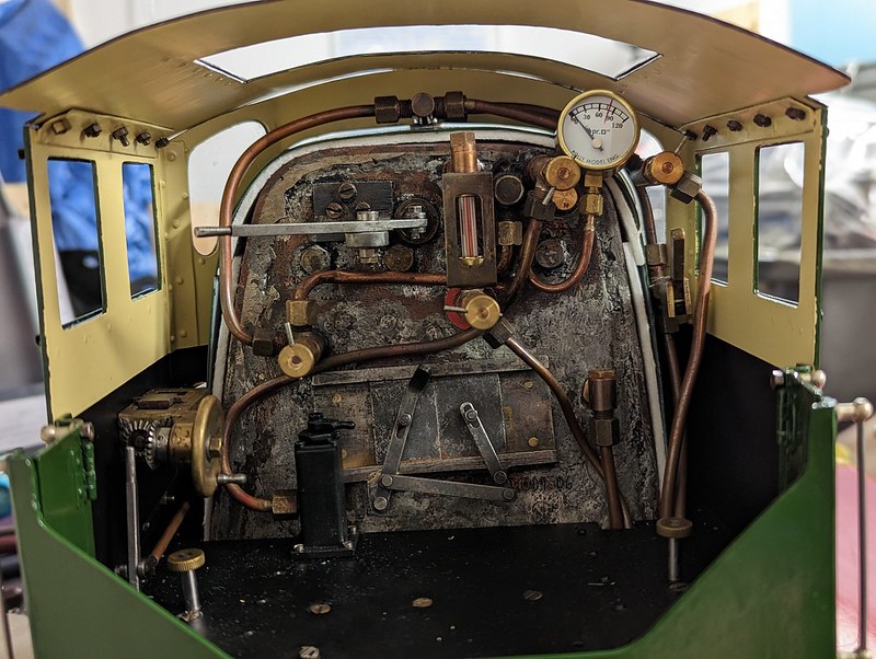 Cab Cab by Daniel Hamblin, on Flickr Cab fully reassembled bar the roof ventilator and the side windows. 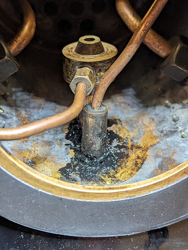 Smokebox Sealing Smokebox Sealing by Daniel Hamblin, on Flickr Not the best work ever but the sealant should fill all the gaps around the blastpipe and snifting valve. I used Geocel Plumba Flue high temperature silicone sealant.  Front End Front End by Daniel Hamblin, on Flickr Front end reassembled all bar the dummy vacuum brake pipe, which I am leaving off while I sort the various snags out.  Blower Set-up Blower Set-up by Daniel Hamblin, on Flickr Blower adaptor machined to match the new petticoat pipe taper.  Loco to Tender Connections Loco to Tender Connections by Daniel Hamblin, on Flickr Loco to tender connections adjusted and test connected. With the whistle fitted the tender pin cannot be dropped into place, so the technique is to remove the loco drag beam pin and secure the tender coupling bar to the tender side. Then drop the pin back in on the loco.  Coupled Up Coupled Up by Daniel Hamblin, on Flickr First time everything has been mounted on loco and tender and the two halves coupled up since 2000. All ready for a first attempt at steaming in over 30 years (our last failed attempt being in 1993).  Test Day Test Day by Daniel Hamblin, on Flickr Locomotive sitting on three pairs of rollers on the lifting table, with the tender on the WorkMate. 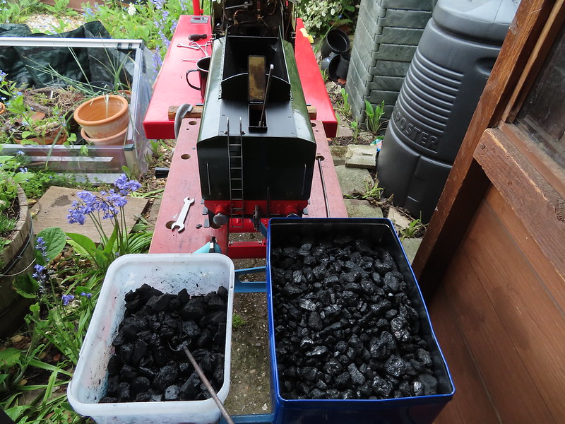 Fuel Fuel by Daniel Hamblin, on Flickr The fuel: charcoal soaked in paraffin (left) and mixed anthracite grains and beans (right). 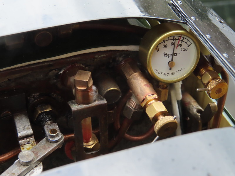 60psi on the Clock 60psi on the Clock by Daniel Hamblin, on Flickr Fire going and pressure has risen to the highest I got - just over 60psi - enough to test things. Slight leak from the top gauge glass fitting cap, which took up after 10 minutes.  Turning Over Turning Over by Daniel Hamblin, on Flickr The motion turning over and steam issuing from the cylinder drain cocks. The regulator wouldn't seal shut so the only way to control things was by using the reverser to move between forward, mid-gear and reverse. One of the jobs will be to lap in the regulator block again. A short video showing performance at 60psi on the gauge - axle pump bypass valve is open and returning water to the tender tank. Bit of a list of jobs to do: - lap in the regulator block again - fix the blower valve that is still leaking - new whistle valve spindle that is a better fit to the valve body and passes less steam - re-pack the hand pump ram - add a better mechanism or access to the firebox throatplate blowdown valve lever - modify oil can to get a smaller pipe that can get into the axlebox tops - replace live steam injector Once I've cleaned the fire remains out this week I can evaluate how well the grate and ashpan changes have worked. I'll take that for a first attempt  Regards, Dan
|
|
|
|
Post by Jim on May 1, 2023 22:01:21 GMT
Hi Dan,
Your Britannia looks fantastic and runs beautifully. It's a very special moment when you steam up your model for the first time, ease the regulater open and see the wheels turn for the first time.
Congratulations on creating a great model.
Jim
|
|
|
|
Post by dhamblin on May 2, 2023 6:38:14 GMT
Thanks Jim, it was certainly a good feeling when the wheels turned under power, even if they shouldn't have at that particular moment!
Regards,
Dan
|
|
|
|
Post by flyingfox on May 2, 2023 6:46:20 GMT
Well done Dan, it's always a great day when the wheels go round with steam.
Regards
Brian B
|
|
|
|
Post by jon38r80 on May 2, 2023 12:15:04 GMT
You must be very satisfied with that, I would be
|
|
|
|
Post by dhamblin on May 2, 2023 18:37:02 GMT
Thanks Brian and Jon, very satisfied. Can't wait to drive it though  Regards, Dan |
|
|
|
Post by dhamblin on Jul 30, 2023 11:26:02 GMT
Close but no cigar...Had the loco in steam for another test session yesterday, so in chronological order:  Hand Pump Ram Hand Pump Ram by Daniel Hamblin, on Flickr Hand pump ram removed for repacking. Fresh graphited yarn was used as the groove is too big to take a standard sized O-ring.  Whistle Valve Whistle Valve by Daniel Hamblin, on Flickr Replacement whistle valve spindle machined from bronze. The original stainless steel one is quite loose in the bore, which allows too much steam to escape rather than getting to the whistle. The thin part of the stem is reduced in diameter to allow more room for steam to enter the valve.  Regulator Block Spring Regulator Block Spring by Daniel Hamblin, on Flickr Spring cap for the regulator block - the idea is that it will bear on the underside of the dome cover and push the regulator block onto the port face. This is bent up from phosphor bronze sheet.  Old Blower Valve Old Blower Valve by Daniel Hamblin, on Flickr Removed the blower valve to clean up the valve face to try and stop it leaking and found the threads suffering from de-zincification. This requires a new valve body to be made out of bronze and re-use the new spindle and end cap I had already made.  New Blower Valve New Blower Valve by Daniel Hamblin, on Flickr New blower valve body and union connections. One more hole needed to be drilled in the body before all three parts could be silver soldered together.  Blowdown Valve Lever Blowdown Valve Lever by Daniel Hamblin, on Flickr Blowdown valve external operating lever made from mild steel flat bar cut and filed to shape, with a fork at one end to go around the existing blowdown valve lever and a pin at the other to allow it to be gripped with a pair of pliers. Forked end is tapped 10BA. Thanks to Roger for the inspiration with this   Blowdown Valve Lever Blowdown Valve Lever by Daniel Hamblin, on Flickr New lever installed, which required the rear driving wheelset to be dropped out to allow access to secure the 10BA stainless steel cheese head screw on the existing valve lever. 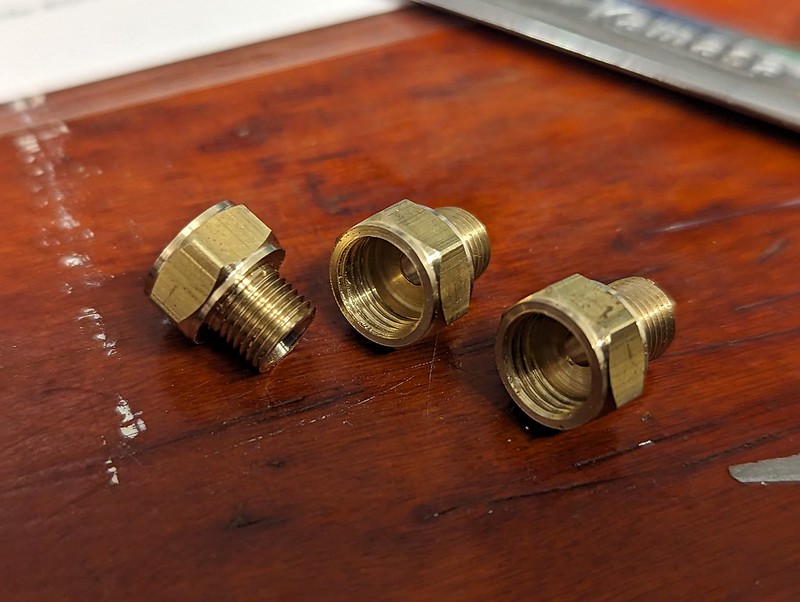 Injector Adapters Injector Adapters by Daniel Hamblin, on Flickr Three adapter unions to attach the new steam injector to existing pipework. Injector end is 5/16" x 32 ME thread and pipework 1/4" x 40 ME thread.  Oil Can Adapters Oil Can Adapters by Daniel Hamblin, on Flickr The Reilang oil can needs a flexible thin copper pipe adding to it for oiling between the frames. Top left is the current spout with its M4.7 x 0.75 thread and below it the new one I have made that allows a standard 1/8" thin wall copper pipe nipple to be secured to it using a 1/4" x 40 thread union nut (bottom right, both from Polly Model Engineering).  Silver Soldered Valve and Pipe Silver Soldered Valve and Pipe by Daniel Hamblin, on Flickr New blower valve silver soldered together as well as a nipple on the copper pipe extension for the oil can. 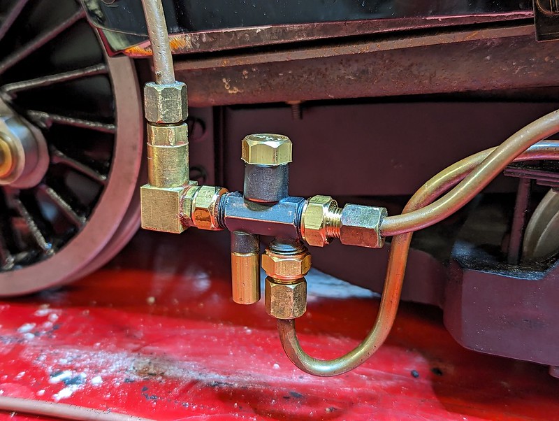 New Injector New Injector by Daniel Hamblin, on Flickr New injector with adapter union attached and plumbed into the water and steam pipework. This is a No. 2 injector (11oz/min feed rate). Re-used the existing clack fitting from the original injector, which has been put aside pending me having a go at making my own injector cones to replace the LBSC design originals.  Test 2 Set Up Test 2 Set Up by Daniel Hamblin, on Flickr General view of the test setup with the lifting table and Workmate used again. Dome cover was left off so I could check the gasket seal was still good and cab roof swung off to check the various modified pipework connections. 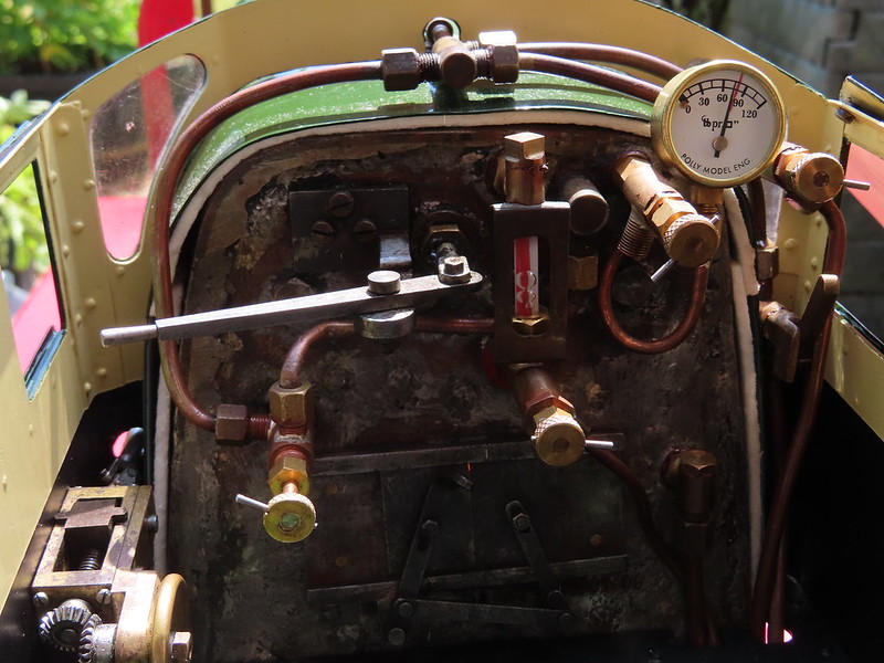 Backhead Backhead by Daniel Hamblin, on Flickr Fire going and pressure as high as it went ~75psi with one safety valve lifting at just over 60psi, which will need resetting on the next test once I've made a tool to do it. The new blower valve (bottom left) worked perfectly. Gauge glass still gets steam bubbles in it normally when the water level is very high, so suspect they are getting trapped now through the top fitting as they appear to descend down the glass. The brake valve pedestal and pipe have been left off pending confirmation the new blower valve worked, as to unscrew it requires the firehole doors to be removed, which can't be done with the brake valve fitted to the footplate. A few videos: Steam bubbles creeping down inside the gauge glass when the boiler water level is high. Pressure gauge at ~75psi and a slight steam leak from the regulator gland which will need nipping up. Motion turning over and steam escaping from the left hand safety valve, which needs resetting to 80psi. Close up of the motion in action along with the faint sound of the exhaust from the chimney, which can be heard with the drain cocks shut. Lots of positives to take: - New blower valve works - Whistle valve modification works (sorry, didn't get a video of it working!) - Hand pump seems to work, although I agree with Jon that it could do with being a bit bigger for the boiler size - Blowdown valve lever works a treat - Modified oil can spot allows oiling up in the hard to reach areas - The fire lights quickly, with working pressure able to be reached and sustained (suggests smokebox seal and grate modifications are all working) On the flip side the new injector didn't work, although I feel that it is a better prospect to start fault finding on than the original LBSC design. A lot of water came out of the overflow with the steam valve on, which suggests the annular gap is too big. Will confirm that on test 3 and make subtle adjustments accordingly. Slight leak on the water feed union, which should be easily fixed. Also need to nip up the axle pump gland and the regulator gland. The big issue is the regulator - the spring cap didn't work as intended. It was sealed shut as pressure rose (an improvement over the first test), but as soon as I opened the regulator it seemed to spring wide open and after that point I couldn't close it. Pulling the handle back to the closed position I encountered a springy resistance, suggesting the block had lifted off the port face. Will take the dome cover off today, but I suspect it has settled back into place. What I could really do with is a clear glass dome cover so I can see what is going on when I open the regulator on first attempt, but that's going to be tricky to achieve. Lots of ideas: - try and lap in situ with a microscope slide between block and port face to act as the flat surface - remove block and investigate whether a PTFE / Flurosint slipper can be fitted (not entirely convinced I can do that without removing the boiler and unscrewing the steam pipe) - bite the bullet and convert to smokebox regulator, which would require new superheaters and re-plumbing the smokebox end Not sure what to do for the best at the moment. Not really comfortable having a regulator that you can't shut, even if the engine can be brought to a stand by putting it in mid-gear. Regards, Dan
|
|
|
|
Post by brucevoelkerding on Jul 30, 2023 13:21:37 GMT
Dan - is the Leak you mention in Water Feed Union supplying the Injector ? A Member at our Club was having a Problem with his Injector. It had worked fine his last time running. I was there and helped him find the Problem. His water Connection between Loco and Tender was just Rubber Hose slipped over Copper Tube with a Hose Clamp. I noticed a slight Water drip from that Connection when the Injector was not in use. The fellow had forgotten to tighten the Hose Clamp. After tightening the Hose Clamp, the Injector worked correctly. Air entering thru the Water Line can easily disrupt the Process inside an Injector.
I suggest you sort out the leaking Union and then re-test the Injector.
|
|
|
|
Post by dhamblin on Jul 30, 2023 20:20:33 GMT
Thanks Bruce that is very good advice and I'll expand it to include a check of the gland packing on the water valve and the pipe connection on it plus both ends of the hose between tender and loco. Struggling to find a small enough removable pipe clip for the latter but I'm sure there is something out there.
Back to the regulator here are a couple of videos showing the mechanism:
This shows the normal action of the regulator block and the amount of play in the mechanism when it reaches the step in the port face. There is quite a bit of vertical play in the block as well.
The regulator mechanism consists of the rod from the backhead, which attaches to a intermediate link that attaches to the main linkage onto the regulator block. The regulator rod is pretty flexible and there are no supports for it inside the boiler, which means it deflects easily when trying to close or open it if the block is not flat on the port face. This can be seen here inside the boiler on the right hand side of the dome hole.
Current thinking is a lapping session to clean up the port face and under side of block, then machine a PTFE / Flurosint cap that is a light interference fit between regulator block and underside of the dome cover.
Regards,
Dan
|
|
mbrown
Elder Statesman
  
Posts: 1,793
|
Post by mbrown on Jul 30, 2023 20:27:48 GMT
I had trouble with a similar regulator valve and discovered that the action of the cross bar in the slot was tending to tip the valve and thereby break the seal with the port face. I wonder how far the point of contact with the cross bar is above the port face? I couldn't work out why mine was tipping, but it certainly was!
I am afraid I changed the whole design in the end....
Good luck with sorting it out.
Malcolm
|
|
|
|
Post by dhamblin on Jul 31, 2023 17:24:39 GMT
Thanks Malcolm, that does tally with what I am feeling when operating the regulator handle. Will play around a bit more - I feel the principle of something to press down on the regulator block is the way to go, just got to work out the optimal design. Certainly not giving up having got this far!  Regards, Dan |
|
|
|
Post by dhamblin on Aug 1, 2023 21:00:05 GMT
Thanks to Malcolm I can now see what the issue is - the regulator block is indeed tipping as it passes along the port face. Possibly more pronounced as the oil / water mix on it dries out (the dome cover has been off since Sunday). Ordered some Fluorosint 500 bar to create a new cap fitting that will fill the space between regulator block and underside of dome cover with a nice wide bearing surface to discourage it from tipping as the bar moves it. Will need to calculate a very slight interference fit at the operating temperature, which might need a bit of trial and error to get right.
If necessary there is plenty of space to fit a Fluorosint slipper between the block and port face, but I'll hold that one in reserve.
Regards,
Dan
|
|