don9f
Statesman
 Les Warnett 9F, Martin Evans “Jinty”, a part built “Austin 7” and now a part built Springbok B1.
Posts: 960 
|
Post by don9f on Jul 20, 2020 20:17:57 GMT
Hi, I built my 9F with a tender that had the curved sides, very like yours but curved along their top and bottom edges. I spent several days building a purpose-made heavyweight bending tool for this job and it was worth it....the actual bending job was done in minutes and came out perfect!
Also, yes I bent them in the “as supplied” state.
At the time, for soft soldering the 16swg brass sheet I used a small butane flame which worked well. Nowadays I know you can buy some very powerful electric soldering irons....300 watts or more. I borrowed one off someone to finish off the tanks on my 3F recently, but they are not that big!
When the time comes to solder the tender tank for the 7F I’m working on, I will use the oxy-propane micro torch. I think the secret is to really localise the heat.
Cheers Don
|
|
|
|
Post by runner42 on Jul 22, 2020 22:57:43 GMT
There is much I don't understand about the front end of the tender, the drawing appears somewhat confusing to me. No doubt it the penny will drop, but in the interim I would like some feedback on the ergonomic use of the tender for being able to load coal into the firebox. The apparent high front appears to prevent coal being easily loaded, on the prototype of course it was the fireman standing in front of the coal door shoveling into the firebox, but on the model the driver is sitting back on the tender or a carriage having to reach over the high front end to reach the firebox. It appears that copying the prototype runs into difficulty in providing an ergonomic solution to firing the model. I may be mistaken, those that have already built a high front tender are in a better position to comment. Pete (greenglade) and Steve (springcrocus) are able to give an informed answer. Brian  tender drg tender drg by Brian Leach, on Flickr |
|
|
|
Post by Jim on Jul 22, 2020 23:33:47 GMT
I had the same problem on the Britannia Brian and the solution for me was to make a suitable section of the front of the tender removable. In this case I made the black painted front removable to give me a nice wide space to access the loco's controls along with tending the fire. This is shows a part view of the front removed. The sharp edges shown here are yet to be covered in this early photo of the tender under construction Because I'm not quite as bendy as I was I made some extender tools to more easily reach the regulator, steam valves and whistle valve. This is the view from the driving carriage. As you can see I made the cab roof removable for greater access and to give a clear view of the back head. Hope this helps, Jim |
|
barlowworks
Statesman
Now finished my other projects, Britannia here I come
Posts: 874
|
Post by barlowworks on Jul 23, 2020 4:32:44 GMT
I have done exactly the same as Jim. Check out my thread, "It started with a buffer".
Mike
|
|
|
|
Post by springcrocus on Jul 23, 2020 7:06:55 GMT
Brian,
Page 19 of my diary covers the front lift-out section of my tender.
Regards, Steve
|
|
|
|
Post by runner42 on Jul 23, 2020 7:54:00 GMT
Thanks for the replies, it obviously is the solution to have a removable section. So during running this is stowed away and is only of benefit as a static model, but with not too much work involved it is worth having it in place.
Reviewing each of your posts I can probably see what the drawing requires for the Black 5.
Brian
|
|
barlowworks
Statesman
Now finished my other projects, Britannia here I come
Posts: 874
|
Post by barlowworks on Jul 23, 2020 8:06:06 GMT
What I found is that you need a good supply of photos of the real thing to work from. On the Brit the drawings are only an approximation of the real thing and are wrong in quite a few details. Also it helps to look at the real thing to help visualise what the drawing is trying to tell you.
Mike
|
|
|
|
Post by coniston on Jul 23, 2020 21:04:40 GMT
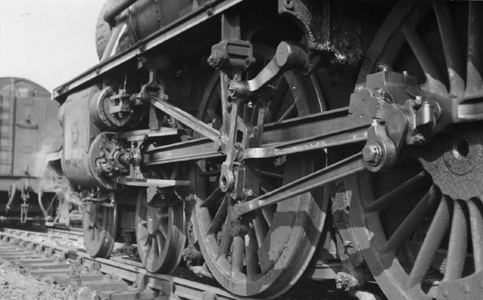
Here's some photos that came from Model Engineers Laser with a kit for a 3 1/2" gauge one scaled from 5" (not sure if Don Youngs or Tony Allcocks Jubilee) May be of some help to you.   ![]()  Chris D |
|
|
|
Post by runner42 on Jul 23, 2020 22:54:05 GMT
Thanks Chris, you can't get plainer than that.
Brian
|
|
Neale
Part of the e-furniture
5" Black 5 just started
Posts: 279
|
Post by Neale on Jul 24, 2020 7:49:43 GMT
I'm at a similar stage with my Black 5 tender. Chassis more-or-less complete and now assembling the body from a Model Engineers Laser kit. I did cheat and bought it with sides ready-rolled at the top, although I was able to curve the front edges (into the cab) by gently beating over a steel bar.
I have drilled all the rivet holes, apart from a few into the rolled top edge for which I need to make a drilling jig. Most of the rivets will be non-structural, so what's the recommendation for fixing in place? I'm currently thinking lightly riveting and maybe then soft solder on the inside, but there will be quite a lot in line with the baffles where I would like them to be flush on the inside. Thoughts, suggestions, and personal experiences welcome!
I have the DY drawings, the Allcock drawings, full-size drawings (from the Wild Swan books), plus many photographs. And the laser-cut plates, of course. None of them agree on almost anything apart from the number of wheels!
|
|
|
|
Post by runner42 on Jul 25, 2020 6:09:30 GMT
OK I am having a moan about DY's drawing for the tender. I understand that he was a professional draughtsman, so from that perspective he is probably more right than I and that I am speaking from a point of ignorance. My problem is I need to find the size of the cut-out in the forward bulkhead. My view, from a practical perspective is that it the measurements should be annotated on the cut-out directly and not require that it is derived from other measurements. What further confuses me is that the available measurements appear irrational, or maybe not, we will see. There is two measurements that doesn't have two referencing lines only one, but is marked with two arrow heads shown with red circles, what does this mean? Brian 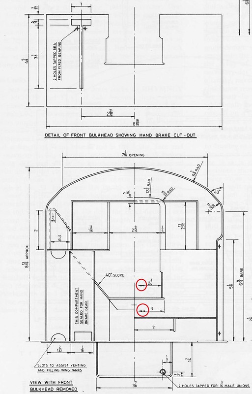 Drawing query Drawing query by Brian Leach, on Flickr |
|
|
|
Post by ettingtonliam on Jul 25, 2020 6:49:15 GMT
Yes,it would have been so simple to dimension the cut-out in the first view wouldn't it?
On the second view, the left hand side is the view without the bulkhead in place, he should have made it clear that its a stepped view, one half looking at the bulkhead,one half looking behind it. Those double arrows mean that its a dimension taken equidistant about the centreline, so the 3" dimension is 1 1/2" either side of centre.
I agree that its a poor example of the draughtsman's art.
|
|
44767
Statesman
Posts: 529
|
Post by 44767 on Jul 25, 2020 21:56:35 GMT
I've bee through all the same troubles. I used Don's drawings for overall dimensions and then reffered to photographs to make it all look right. Don't be fooled by Don's interpretation of the bulkhead. There is only one tool locker which is on the driver's side of the coal space access doors. The firing iron storage tunnel is my wider that Don has drawn it. Refer to photographs if you're using Don's drawings or use the Allcock drawings as that is a very good set of drawings.
|
|
|
|
Post by Jim on Jul 25, 2020 22:50:59 GMT
I couldn't agree more with 44767's comments on the value of photos of the prototype with regard to getting the details right. I had exactly the same issue with the Perrier drawings for the Britannia.
Apart from details of fittings etc the access space created by removing part of the front of the tender as drawn by Perrier was far too narrow and restricted making firing difficult and more than likely causing injuries to hands. Part of the challenge of this hobby is to create a model that accurately represents the prototype while incorporating very discrete modifications that make it workable for our non scale hands. 
Jim
|
|
barlowworks
Statesman
Now finished my other projects, Britannia here I come
Posts: 874
|
Post by barlowworks on Jul 26, 2020 7:25:27 GMT
Something else to think about. I'm not sure about your tender but on the Britannia there is a space between the front bulkhead on the coal space/tank and the tender front for the brake and water pick up gears and the lockers. When the removable section is not in place this is open and I could imagine me filling it up with coal when firing. My solution was to make two clip in covers to cover up this area when running. As I said just something to think about, you don't want to be turning the tender upside down to empty it out. ☹️
Mike
|
|
|
|
Post by runner42 on Jul 26, 2020 8:01:45 GMT
I'm at a similar stage with my Black 5 tender. Chassis more-or-less complete and now assembling the body from a Model Engineers Laser kit. I did cheat and bought it with sides ready-rolled at the top, although I was able to curve the front edges (into the cab) by gently beating over a steel bar. I have drilled all the rivet holes, apart from a few into the rolled top edge for which I need to make a drilling jig. Most of the rivets will be non-structural, so what's the recommendation for fixing in place? I'm currently thinking lightly riveting and maybe then soft solder on the inside, but there will be quite a lot in line with the baffles where I would like them to be flush on the inside. Thoughts, suggestions, and personal experiences welcome! I have the DY drawings, the Allcock drawings, full-size drawings (from the Wild Swan books), plus many photographs. And the laser-cut plates, of course. None of them agree on almost anything apart from the number of wheels! Hi Neale, where did you get the pattern of dummy rivets from? Brian |
|
|
|
Post by suctionhose on Jul 26, 2020 10:15:20 GMT
Yes,it would have been so simple to dimension the cut-out in the first view wouldn't it? On the second view, the left hand side is the view without the bulkhead in place, he should have made it clear that its a stepped view, one half looking at the bulkhead,one half looking behind it. Those double arrows mean that its a dimension taken equidistant about the centreline, so the 3" dimension is 1 1/2" either side of centre. I agree that its a poor example of the draughtsman's art. As the Engineer we have become acquainted with, your comment is reasonably equated with your experience of organisations responsible for construction of major infrastructure. However, I have stood, with Don Young, in his 4 X 6ft room where all this took place. I imagine Martin Evans and Co were not much better off in resources, and so I am staggered by the amount of stuff they produced whatever the deficiencies! I have designed a few of my engines from scratch. Much less produced drawings for sale - or heaven forbid - a set castings... You have no idea how difficult the task it is. Certainly the DY's and ME's (Ernie Winter in Aust too) etc set themselves up for some criticism but, to be fair and reasonable to them, we should be grateful for what they've provided for us - gaps and all. |
|
Neale
Part of the e-furniture
5" Black 5 just started
Posts: 279
|
Post by Neale on Jul 26, 2020 10:35:40 GMT
Good question, and I refer the honourable gentleman to my last sentence! DY is unhelpful on the topic - I seem to remember him saying that you can put them in or not, but they are not marked on his drawings (although it's a while since I looked at the DY tender drawings). Allcock is more useful and gives detailed location and spacing of rivet positions although it's difficult to find all the data on the drawings at first sight. This is great if you are building a tender with his internal structure, which I am not as I am using the MEL kit! So, what I have done is to use some of the Allcock information, particularly rivet spacing, together with photographs (published and my own) of real tenders, and tried to put together something which is realistic in appearance while matching things like internal baffle positions. So, I counted rivets on the real thing, worked out spacings, and then varied them slightly (both in number and spacing) so that it looked about right. For example, the internal baffles are not quite evenly spaced, so while I have the correct number of rivets between baffles, the spacing is very slightly varied to suit. Subtle and the variation in spacing does not show in practice. I shall fail the true rivet-counter test, but it will impress the ignorant! All that info went into my Fusion 360 tender model and I was then able to CNC spot and drill the rivet holes to ensure accurate hole positions. Nothing worse than a rivet slightly out of line! Stupidly, I measured the rivet shanks, selected a drill, drilled all the holes, and then found that the rivets were slightly too tight in the holes. So I ended up opening them out to the next drill up (1.2mm to 1.3mm) to give the right fit. Last night I tried fitting some rivets - fluxed the line of holes on the inside, pushed the rivets through and bent them over slightly to stop them falling out, and soft-soldered with my finest propane nozzle. Worked OK, I think. I also fitted some rivets to a trial piece of brass to see what happened when I filed them down flush inside. Looks OK, so I think I have the basis of the technique for fitting the dummy rivets (where they align with internal flanges and angle pieces) while leaving some holes empty so I can drill right through and use those for alignment, if not actually being structural (i.e. may or may not get riveted over or soldered - I'll see how that goes). I'm happy to pass on my F360 model to anyone if that would be useful (or give light entertainment, according to taste...)  tender body front three-quarter tender body front three-quarter by Brian Neale, on Flickr  tender body rear three-quarter tender body rear three-quarter by Brian Neale, on Flickr |
|
|
|
Post by ettingtonliam on Jul 26, 2020 11:10:58 GMT
As the Engineer we have become acquainted with, your comment is reasonably equated with your experience of organisations responsible for construction of major infrastructure. However, I have stood, with Don Young, in his 4 X 6ft room where all this took place. I imagine Martin Evans and Co were not much better off in resources, and so I am staggered by the amount of stuff they produced whatever the deficiencies! I have designed a few of my engines from scratch. Much less produced drawings for sale - or heaven forbid - a set castings... You have no idea how difficult the task it is. Certainly the DY's and ME's (Ernie Winter in Aust too) etc set themselves up for some criticism but, to be fair and reasonable to them, we should be grateful for what they've provided for us - gaps and all. To the contrary, I have designed my own planer, produced the drawings on an A2 drawing board with parallel motion, as I was taught over 50 years ago, made the patterns and machined the castings, so yes, I think I do know how difficult the task is. Don Young, so we are often told, was a profesional draughtsman, and so I would have expected better of him in this instance, however small his room was. Granted, generally, his drawings seem to better than some I could mention. Richard |
|
Neale
Part of the e-furniture
5" Black 5 just started
Posts: 279
|
Post by Neale on Jul 26, 2020 11:47:36 GMT
Don Young, so we are often told, was a profesional draughtsman, and so I would have expected better of him in this instance, however small his room was. Granted, generally, his drawings seem to better than some I could mention. Richard I'm sure that he would have done a better job had he been able (and willing?) to use modern 3D CAD! The clash between the tender front wheels and the front drag beam leaps out at you when you see it as a 3D model, but would be difficult to pick up from 2D drawings. I am modelling the Black 5 tender as I go along in Fusion 360, partly to be able to visualise better a fairly complex structure and partly as a cross-check of the drawings. In practice, though, I realise that I am not actually checking the drawings that much because having taken off key dimensions (frame spacing, that kind of thing) the other bits are modeled to fit, rather than to specific dimensions. Given that wherever possible, I go from 3D model to CNC toolpaths, I skip the whole "engineering drawing" stage altogether. That kind of thing is just so twentieth century...
I'm joking, of course, but it does make me wonder if, sometime soon, published designs would be better produced as 3D models, so that builders can produce drawings for manual machining or directly to CNC toolpaths as needed.
|
|