|
|
Post by runner42 on Jul 27, 2020 0:17:32 GMT
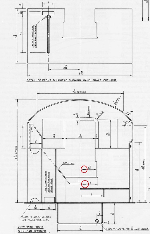
OK I am having a moan about DY's drawing for the tender. I understand that he was a professional draughtsman, so from that perspective he is probably more right than I and that I am speaking from a point of ignorance. My problem is I need to find the size of the cut-out in the forward bulkhead. My view, from a practical perspective is that it the measurements should be annotated on the cut-out directly and not require that it is derived from other measurements. What further confuses me is that the available measurements appear irrational, or maybe not, we will see. There is two measurements that doesn't have two referencing lines only one, but is marked with two arrow heads shown with red circles, what does this mean? Brian  Drawing query Drawing query by Brian Leach, on Flickr I suppose I should have not expressed my frustration on DY drawing style and kept my inquiry to resolving his more esoteric method of delineating measurements. It would not have resulted in the need for others to respond to any negative comments made. I agree it is a monumental task and I hope that he was rewarded for his efforts. On reflection, he probably didn't intend to produce a piece part drawing of the bulkhead, but was faced with providing the cut-out dimensions for the hand break and decided that it was too crowded to add it to the existing front view. Having defined the dimension for the cut-out in the lower drawing, considered it was unnecessary to re-define it on the piece part drawing. For me if he had produced piece part drawings for all parts of the front view then it would have been more obvious to what is required. Brian |
|
|
|
Post by suctionhose on Jul 27, 2020 2:26:59 GMT
As the Engineer we have become acquainted with, your comment is reasonably equated with your experience of organisations responsible for construction of major infrastructure. However, I have stood, with Don Young, in his 4 X 6ft room where all this took place. I imagine Martin Evans and Co were not much better off in resources, and so I am staggered by the amount of stuff they produced whatever the deficiencies! I have designed a few of my engines from scratch. Much less produced drawings for sale - or heaven forbid - a set castings... You have no idea how difficult the task it is. Certainly the DY's and ME's (Ernie Winter in Aust too) etc set themselves up for some criticism but, to be fair and reasonable to them, we should be grateful for what they've provided for us - gaps and all. To the contrary, I have designed my own planer, produced the drawings on an A2 drawing board with parallel motion, as I was taught over 50 years ago, made the patterns and machined the castings, so yes, I think I do know how difficult the task is. Don Young, so we are often told, was a profesional draughtsman, and so I would have expected better of him in this instance, however small his room was. Granted, generally, his drawings seem to better than some I could mention. Richard Apologies. I meant "You" in a general sense of "People". To be fair to those brave souls that have produced designs for people to follow, in consideration of the meager returns they received, I think, even with a few frustrations, the designs are still extraordinary value. |
|
|
|
Post by suctionhose on Jul 29, 2020 12:23:57 GMT
|
|
|
|
Post by suctionhose on Jul 30, 2020 23:41:14 GMT
I meant to post this as well - the 4000 Gal tender. Maybe you can scale what you need from it?  |
|
|
|
Post by runner42 on Jul 31, 2020 8:02:09 GMT
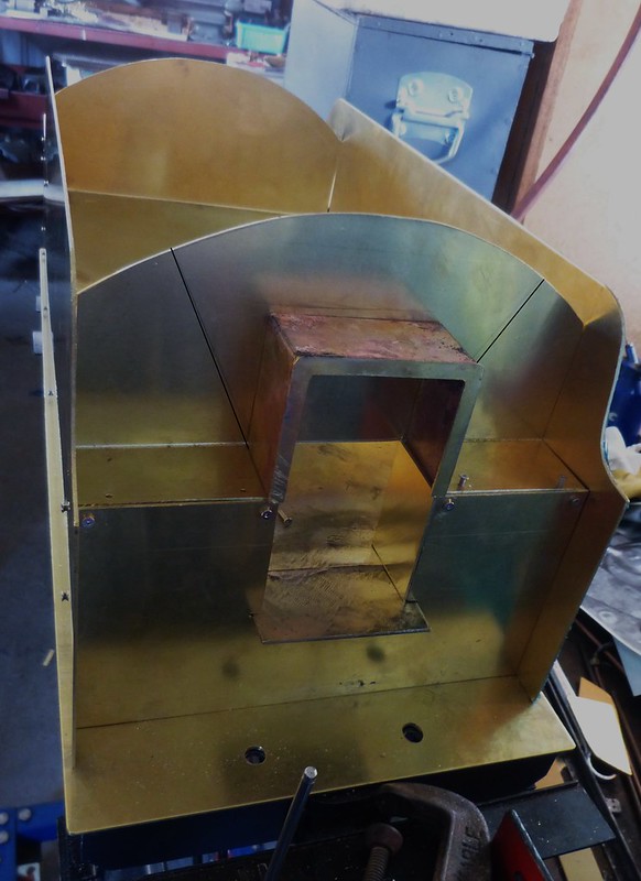
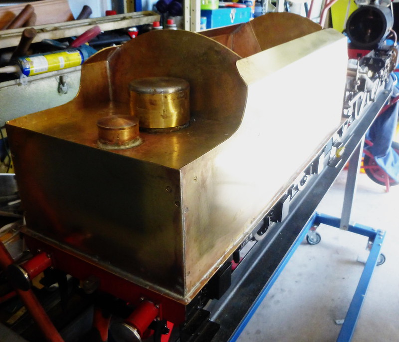
I was always going to deviate from DY's drawing requirements, since it is not the first time I have changed things. The coal space has been altered leaving out the more complicated requirements for the addition of space provided for tools that were required by the platform crew on the fullsize locomotive, but something not essential for the model. The coal space is more aligned to LBSC's Doris. However, I am following as far as practicable the front end looking rearward. I have not finished the coal room doors or have attempted to finalise the joining of parts. I have adopted Steve's approach of using small BA screws until I am satisfied that every thing is going to come together reasonably well for soldering. I did however, silver solder the coal door enclosure as I didn't want it to fall to pieces if soft soldered and applying heat in close proximity areas. The reason for the interim post is to seek advice on where the cut is made to remove the centre section for easy access to the locomotive's back head. From the information provided by Chris in the earlier photographs the cut is made as I have shown by the two black lines in the first photograph. The centre section is to include the coal door enclosure and the adjacent box. However the lower miniature hinge for the coal door is affixed to the non removable section so I assume that the cut needs to include some of the lower areas. Any information is welcomed.  tender body tender body by Brian Leach, on Flickr I have made the large dome removable and it will be the access to the emergency pump.  tender body1 tender body1 by Brian Leach, on Flickr  tender body2 tender body2 by Brian Leach, on Flickr Brian |
|
Neale
Part of the e-furniture
 5" Black 5 just started
Posts: 283 
|
Post by Neale on Jul 31, 2020 9:06:28 GMT
I'm planning to leave off the bottom hinge - it won't notice to anyone except an expert (and they will be too busy criticising everything else anyway!) and I don't think that it is structurally necessary at this scale.
I'm also going to make the large dome removable for the same reason - plenty of room to swing the hand pump lever.
I'm currently at "fitting rivets" stage. My wife, "Why have you just drilled 1500 holes in that when it's supposed to be watertight?"
|
|
barlowworks
Statesman
  Now finished my other projects, Britannia here I come
Posts: 878 
|
Post by barlowworks on Jul 31, 2020 15:42:47 GMT
Hi Brian, it all depends on which version you are going to model. If you are having the two lockers like in the drawings I would extend the cut from the corner of the lockers to the point where the side sheet joins to the front. If not I would still aim for that point anyway, you should be able to get a nice clean shape that way rather than halfway down the top. As for the dome, I made the entire back removable, plenty of room to swing the hand pump lever then.
Mike
|
|
|
|
Post by Jim on Aug 1, 2020 9:05:45 GMT
I've done much the same as Mike in that I selected a path for the cutout/liftout section of the tender front that was neatly disguised by locker edges and panel joints. As mike has done the rear deck of the tender lifts off with the ladder a separate and easily removable. While I don't have a manual pump in the tender having the rear deck easily removable gives me access to the tender's inner fittings such as the water filters on the injector feeds , drain plug and overflow pipe. Jim |
|
|
|
Post by runner42 on Aug 13, 2020 7:33:23 GMT
I made an emergency hand pump for the tender, made from mainly scrap bin material to my own design, but without giving it too much thought. It is 3/8" bore X 1 1/4" stroke, but when I placed in in the tender it is dwarfed by the size of the water space. The operating handle to extend beyond the large top opening will have to be long such that the throw at the top will be too great for the diameter of the top opening to realise the 1 1/4' stroke of the pump. The only solution would be to raise the pump off the sole plate by a few inches, but this would have negative consequences. The reason for this inquiry is to determine what size of pump would be necessary for a 5" gauge Black 5, preferably a design drawing would cover all my needs. Brian  emergency hand pump emergency hand pump by Brian Leach, on Flickr |
|
|
|
Post by John Baguley on Aug 13, 2020 8:07:38 GMT
Brian, that pump will be far too small to be of much use. You'll spend all day trying to put any water in.
You really want 5/8" bore minimum for a large 5" loco like the Black 5, maybe even 3/4" bore. I use 1/2" bore pumps for 2½" gauge locos.
John
|
|
barlowworks
Statesman
  Now finished my other projects, Britannia here I come
Posts: 878 
|
Post by barlowworks on Aug 13, 2020 13:37:55 GMT
Putting the hand pump on a box is not a problem, with a bit of lateral thinking you can turn it to your advantage. On my Britannia I mounted the hand pump onto what I call my filter box.
This box is fed by two filters intended for filtering fish tanks. All water intended for the loco has to go through this box so it is all filtered. I fitted the stop taps so the tender tank would not empty if full and not connected to the loco. Check out my thread for more details or drop me a PM.
I did have to get a bit imaginative with the operating handle but it all works fine.
And I do think your pump is a little small for 5 inch gauge. 
All the best
Mike
|
|
|
|
Post by runner42 on Sept 7, 2020 3:30:36 GMT
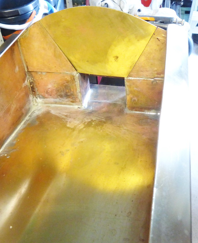
An update showing progress on the tender body. I chose to use small brass hinges for the doors, they are available on ebay and are used primarily for doll's house furniture. The hinges because of their size are not robust enough that they take a lot of operation, which i did and eventually broke the middle one on the LHS, so I shall replace it and keep the operation to a minimum.  tender front_exposure tender front_exposure by Brian Leach, on Flickr  tender rear_exposure tender rear_exposure by Brian Leach, on Flickr  tender side_exposure tender side_exposure by Brian Leach, on Flickr  tender inside_exposure tender inside_exposure by Brian Leach, on Flickr A lot of work to do still on affixing the trim, under chassis plumbing. The emergency hand pump is a 5/8" bore x 1.25" stroke and I copied the valve arrangement from the drawing in Steve's (springcrocus) post but may need to alter the ball size to hole size because it doesn't push enough water out per stroke. What is the best arrangement to have in the pump of this size? Brian |
|
mbrown
Elder Statesman
  
Posts: 1,790
|
Post by mbrown on Sept 7, 2020 7:59:55 GMT
Beautifully neat soldering Brian - not easy with that quantity of brass.
Malcolm
|
|
|
|
Post by coniston on Sept 7, 2020 12:33:11 GMT
Coming on really well Brian, some neat work there.
Chris D
|
|
|
|
Post by runner42 on Sept 8, 2020 7:55:18 GMT
Having fill the tender with water and no leaks, the issue arose of how to empty the tender, not at this juncture but when after a run. Having a full tender adds to the handling weight and the possibility of water spillage in transport, so I think that it would be a good idea to add a drain plug. Is this the general practice, particularly on the larger 5" gauge and if so what type of drain valve would be appropriate?
Brian
PS I am following John's (simplyloco) use of spray gun filters for the water filtration in the tender. In anticipation of these on order will arrive soon I would like to ensure that the mating of the filter to the brass pass through the soleplate device is correct, I would appreciate if John could outline how the mating is achieved.
|
|
|
|
Post by springcrocus on Sept 8, 2020 8:08:14 GMT
Brian, I know you've seen this before but, just as a reminder, THIS is what I did. You may be able to devise something similar. Regards, Steve |
|
|
|
Post by Deleted on Sept 8, 2020 8:11:59 GMT
Hi Brian, the tender is looking great sir...re drain plug/ I guess that would depend on how large your water feed pipes are? I did a test on my tender by just opening both injector globe valves fully to see how fast the water came out, I didn't time it but it didn't take long for the tender to empty, the pipework on 4472 is 1/4" OD. Somewhere back in my build thread I did include a picture of the tender emptying, there were two large water spout jets shooting a few feet out of the tender.
regards
Pete
|
|
|
|
Post by simplyloco on Sept 8, 2020 8:22:16 GMT
Having fill the tender with water and no leaks, the issue arose of how to empty the tender, not at this juncture but when after a run. Having a full tender adds to the handling weight and the possibility of water spillage in transport, so I think that it would be a good idea to add a drain plug. Is this the general practice, particularly on the larger 5" gauge and if so what type of drain valve would be appropriate? Brian PS I am following John's (simplyloco) use of spray gun filters for the water filtration in the tender. In anticipation of these on order will arrive soon I would like to ensure that the mating of the filter to the brass pass through the soleplate device is correct, I would appreciate if John could outline how the mating is achieved. Hi Brian. It screws (moulds itself) onto the existing 5/16" x 32 thread. Easy! John |
|
|
|
Post by David on Sept 8, 2020 8:25:28 GMT
It's common to have a drain plug in our club. I soldered the one in the B class tender but that distorted the floor. You're obv better at soldering than me so you might get away with it.
If there's a next time I'd consider something with threads and an o-ring that isn't permanently attached to the tender floor.
In contrast to Pete's experience I find it takes forever for the red loco's tender to drain through the pipes. Plus I have the filter/outlets 10 or 15mm off the tender floor from when we thought rubbish was getting to the injectors from rust flaking off so there's a decent amount of water left in it even when it's 'finished' draining.
|
|
barlowworks
Statesman
  Now finished my other projects, Britannia here I come
Posts: 878 
|
Post by barlowworks on Sept 8, 2020 9:07:17 GMT
Johns solution also works for me but I forgot the drain holes at floor level so have a bit of water left in the tank when empty, easily removed with a length of plastic tube syphon and a block of wood under the front wheels.
Mike
|
|
 Drawing query by Brian Leach, on Flickr