mbrown
Elder Statesman
  
Posts: 1,790
|
Post by mbrown on Jul 12, 2018 6:38:11 GMT
Another advantage of the parallel front section is that fitting the tube plate - and in some cases the smoke box ring - is a great deal easier.
And if you can do one circumferential joint properly, two should hold no fears.
Malcolm
|
|
|
|
Post by runner42 on Jul 20, 2018 3:15:24 GMT
Made the expansion link assemblies, but as a precursor to soldering the various parts I made the expansion link bearings and fitted them to their respective sides. In assembly I also fitted a piece of 7/32" dia rod to simulate an expansion link to sit between the bearings. This was to ensure that the orientation of the bearings in their respective sides were in line so that when the soldering the various parts occurred there was no movement to cause binding in the bearings when the expansion link was finally fitted. However, I was victim to one of Don Young's initial drawing errors, in so much that he depicted the bearing length as 15/32" which when a 21/32" expansion link was fitted between a frame width of 7/8" did not compute. 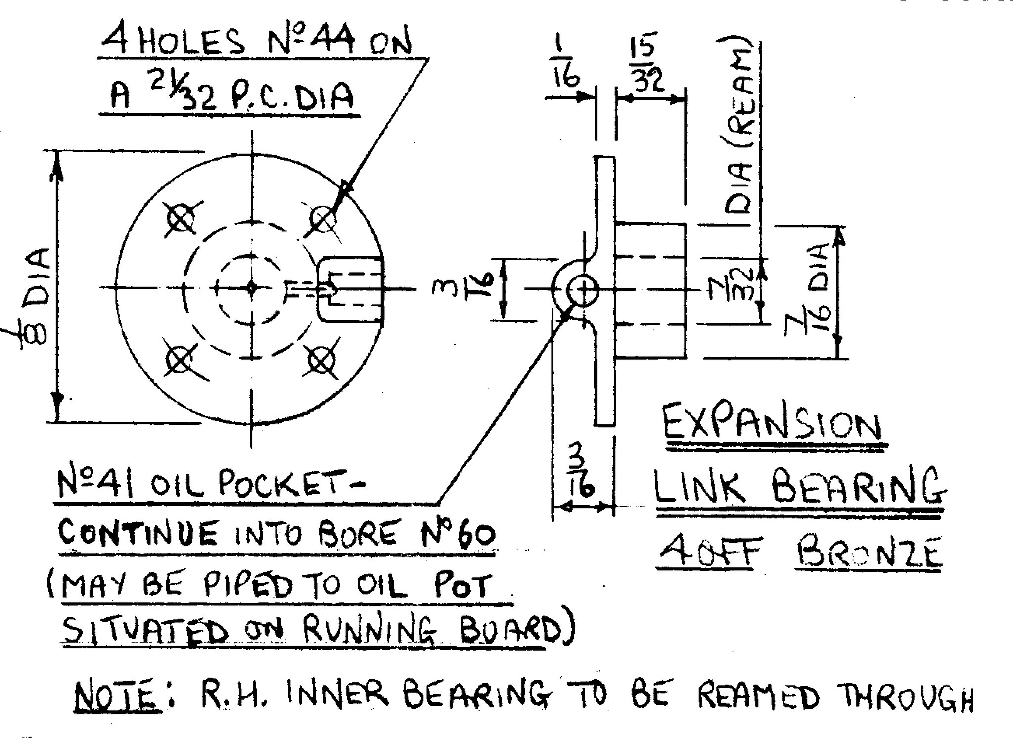 expansion link bearing expansion link bearing by Brian Leach, on Flickr 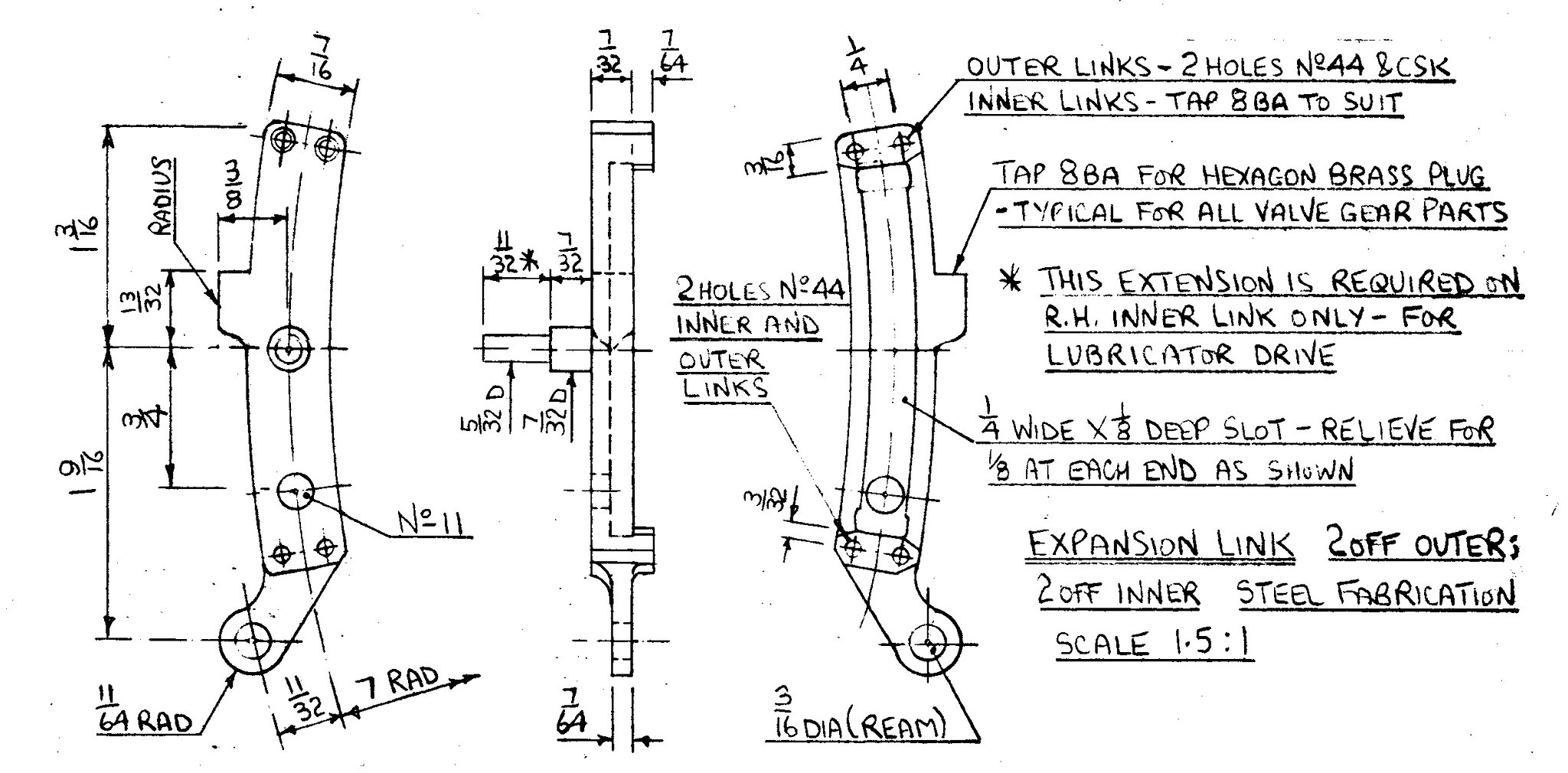 expansion link expansion link by Brian Leach, on Flickr I have subsequently been advised that the bearing length is 15/64" and not 15/32". I had to make 4 new bearings which was the lesser of two evils in trying to reduce the length of the oversize ones. Brian |
|
|
|
Post by runner42 on Aug 1, 2018 1:52:18 GMT
Having completed the expansion links, I searched the relevant drawing for the measurements of the applicable die block. After much head scratching I searched his words and music and found that he had unapologetically not included the requirements on the drawing but to prevent further queries detailed the requirements in the narratives. There he gave an insight to the purpose of the no 11 hole, which also had foxed me, apparently it is to enable the radius rod pin(s) to be inserted into the expansion link. In the same paragraph he also provided a method to prevent silver solder from ingressing into the radius slot. This lack of information on the drawings, requiring other media to complete the construction reminds me of the time working for an Australian co producer with an American prime on a Fighter project, it was found that in the technology transfer, that a lot of information was omitted from the drawings because it was entrenched in the prime's workmanship standards. So the task for the co-producer was more onerous than first expected.
I am going to make some changes to Don Young's design only subtle but to align it with my methods of construction. The expansion links is one such place. I am going to silver solder each half of the expansion link only and use screws to affix the two halves, this way I can disassemble the expansion link and get to the die block if required. The no 11 hole will become redundant.
Brian
|
|
|
|
Post by Deleted on Aug 1, 2018 6:25:29 GMT
Hi Brian
yes, Don has a habit of that, best to read through the entire words a few times first.....having said that I still find bits and pieces that I either didn't read properly or just plain forgot.
keep up the good work.
Pete
|
|
stevep
Elder Statesman
  
Posts: 1,073
|
Post by stevep on Aug 1, 2018 7:59:57 GMT
Let's see some pictures, Brian.
|
|
|
|
Post by runner42 on Aug 2, 2018 6:53:19 GMT
This is the bits I have made so far. My subtle change to DY's expansion links have run into a bit of a problem because of the protrusions of the screw and nut prevents installation into the expansion link bracket top cut-out. I will have to counter sink and use the appropriate screws. Brian 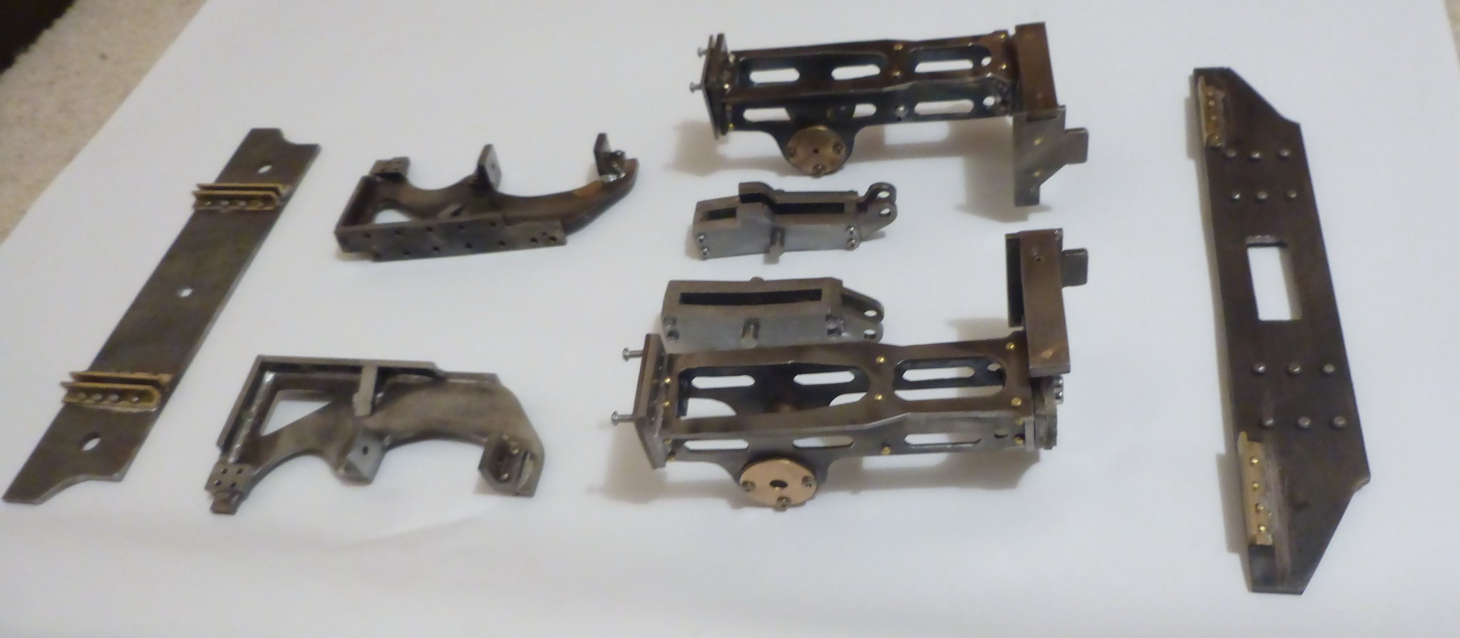 bits so far bits so far by Brian Leach, on Flickr |
|
Lisa
Statesman
 
Posts: 806 
|
Post by Lisa on Aug 2, 2018 8:09:39 GMT
That's some nice looking fabrications there Brian, you should be pleased.
|
|
|
|
Post by runner42 on Aug 2, 2018 22:48:30 GMT
|
|
|
|
Post by runner42 on Aug 3, 2018 8:29:16 GMT
That's some nice looking fabrications there Brian, you should be pleased. Thanks Lisa, I still have to add some embellishments by adding facings to the motion plate and the expansion link bracket, now that I have some 1/16" plate that can readily bent around the curved surfaces. Hack sawing filing and soldering is a mainstay of my construction techniques, however I should attempt to use the mill to produce the parts. However as you realise that my lack of milling experience makes the task somewhat protracted since I have no experience in how to set the job up so that milling can be readily undertaken. Today, I spent a few hours trying to hold a job firmly so that I could mill it. It wasn't successful so I reverted to my old methods. Not the best approach as I wont learn. Brian |
|
|
|
Post by mr swarf on Aug 3, 2018 8:59:24 GMT
Don't be too hard on yourself, finding out how not to do something is all part of learning. I've made a mess of a few parts in the past finding out how not to do it.
Paul
|
|
|
|
Post by runner42 on Aug 8, 2018 1:43:20 GMT
Advice please on how to construct the motion plate girder. As you see that the material thickness is only 1/16" and it is the traditional girder cross section. Very difficult to pin before soldering. I suspect that a jig would be required to hold it so the middle vertical section sits halfway between the top and bottom horizontal sections and the three pieces are square to each other. Thanks in advance. Brian. 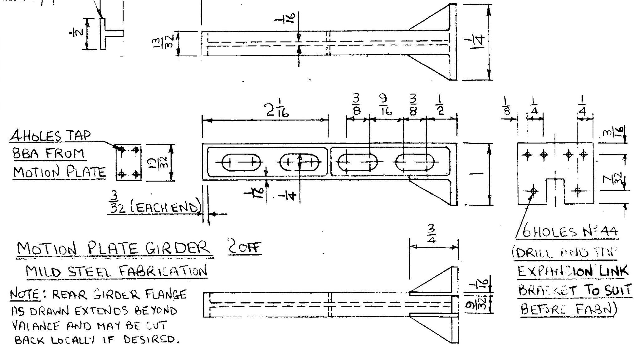
motion plate girder by Brian Leach, on Flickr PS Having read the construction notes I now realise that it is made from a solid steel bar and milled each side to a depth that leaves a 1/16" centre piece. Wow that's a milling task to start with. |
|
|
|
Post by runner42 on Aug 8, 2018 7:15:38 GMT
Not the best but they are functional more than pretty. I soldered first using small clamps and then pinned, so subsequent solder operations don't cause collapse of the work done so far. I'll decide if I attempt the milled version at a later date, when I have gained experience in milling. Brian 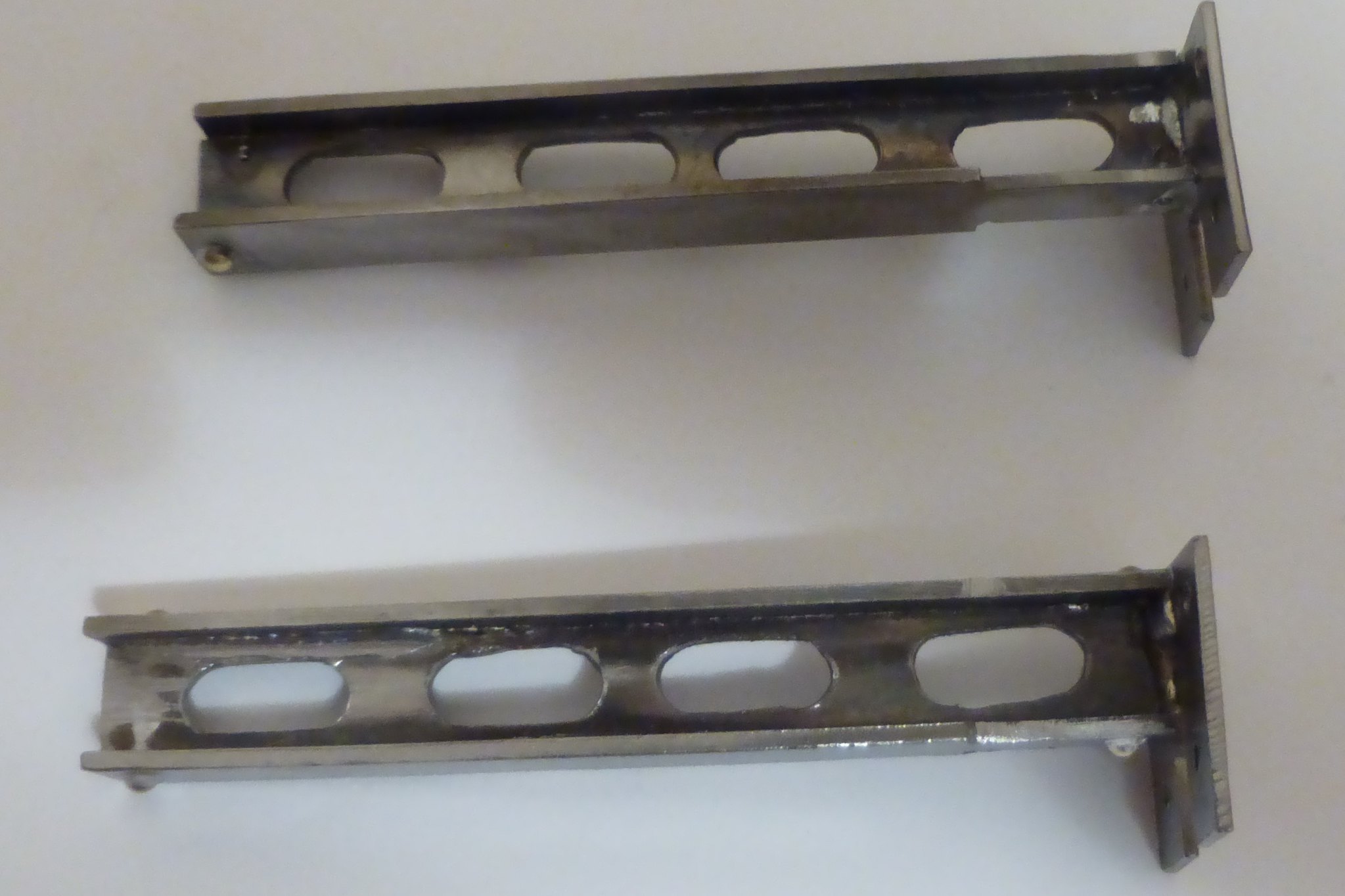 motion girders motion girders by Brian Leach, on Flickr |
|
stevep
Elder Statesman
  
Posts: 1,073
|
Post by stevep on Aug 8, 2018 7:54:26 GMT
Looks like you made a fine job there, Brian.
If you look at Roger's thread, then that wouldn't be a big milling job at all. He mills 40 mm bar down to 0.6 mm!
|
|
|
|
Post by Roger on Aug 9, 2018 14:41:13 GMT
Not the best but they are functional more than pretty. I soldered first using small clamps and then pinned, so subsequent solder operations don't cause collapse of the work done so far. I'll decide if I attempt the milled version at a later date, when I have gained experience in milling. Brian  motion girders motion girders by Brian Leach, on Flickr Hi Brian, That all looks good to me, there seems little point in machining one from solid if it's accurate enough anyway. If I was machining the main girder part of that from solid, I'd still attach the big plate on the end as a separate piece because that's an awful lot of metal to remove and there's no point. I'd machine a register in the end plate and leave a tongue on the girder part so they could be 'riveted' together while it was being Silver Soldered. |
|
|
|
Post by runner42 on Aug 11, 2018 7:21:33 GMT
I am constantly being challenged by DY construction requirements. Today's challenge is to make the frame stays, the difficult part is putting bends in sheet steel where the bend occurs close to material edge and that prior to bending cut-outs have been made that considerably reduces the ability of the material to retain its shape. In addition four bends are required to produce a tray configuration and after bending the frame stay has to meet a specified measurement in both directions. Firstly does the material need to be heated to assist the bending? When bending is it better to clamp the edge (tray side) and apply force to the larger area (tray base) (bigger moment) or clamp the larger area and apply force to the edge? The first approach causes distortion of the tray base due to the cut outs being close to the bend, the latter approach is more difficult because of the smaller moment requires a greater force. In meeting a specified measurements for the footprint of the tray base, where does the bends need to occur, if for example the outside distance of the edges is 4 1/2" does the bend lines need to be marked at 4 1/2" minus the material thickness for each side? This at first appears self evident but the bend is never a perfect corner and some radius in the bend generally occurs? A seemingly easy item to make but it contains a few hidden snags. I was tempted to just produce the tray base and rivet four angle iron (steel) pieces to form the edges. Any recommendations are gratefully received. Brian 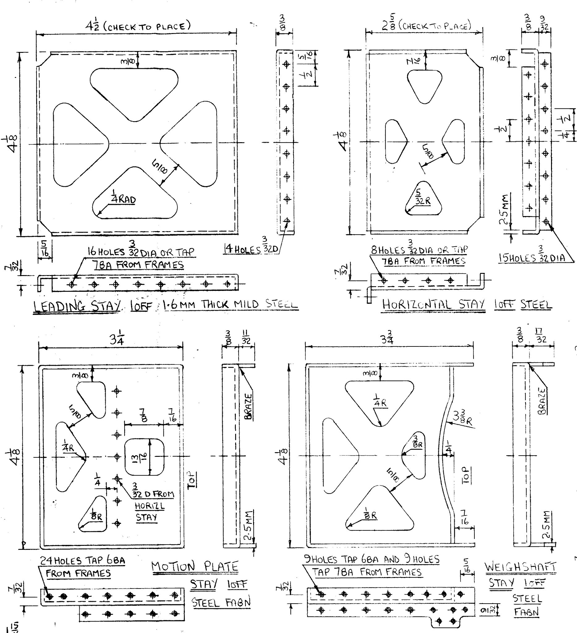 Frame stays Frame stays by Brian Leach, on Flickr |
|
|
|
Post by ettingtonliam on Aug 11, 2018 7:42:31 GMT
I'd be tempted to make steel formers and backing plates, same as with boiler plate formers, clamp up, and tap the flanges over that. A lot of work, but you should end up with sharp bends, and, if the former is the right size, the width over flanges should be right. Using this method, you should be able to form the cut outs before bending without distortion. If the material is cold rolled, you should probably anneal it first to avoid cracking. Bending thin material like this hot isn't really possible, it cools down too quickly. Fabrication might be easiest.
|
|
|
|
Post by simplyloco on Aug 11, 2018 8:04:07 GMT
I would do the cut outs afterwards, probably with a big file...  |
|
|
|
Post by miketaylor on Aug 11, 2018 8:54:59 GMT
Worth looking back through Roger's Speedy thread.
He has done some very nice tight bends using formers but I like his method of machining a vee groove part way through on the line of the bend which defines the bend very clearly and makes a very neat accurate bend and then silver soldering the bent area on the inside to give back the strength.
Mike
|
|
|
|
Post by Deleted on Aug 11, 2018 9:29:36 GMT
I'd agree with using 'steel formers', yes the material will need annealing, some parts are 2.5mm thick. Using steel formers I'd cut out the shape leaving the sides overlength, if the formers are made from a material thickness that matches the height of the sides when formed you could use this to keep the part solid while milling off the excess material, remember to allow for the metal thickness when working out former thickness. Also with the former still in the part with the sides machined down to size the part can be held in the machine vice for milling the sides to square to fit between the frames. If using this method I'd probably do the cutouts first and only anneal the tabs(sides) ready for forming. Alternatively, again as already pointed out you could fabricate the part, this would probably take more time though.
Well, I wrote all this and before posting took another quick look at the drawing...on the second look some of this will have to be fabricated, perhaps doing most of it that way may be a prudent move...some parts are simple bends, do those and fabricate the rest.....others who have built this loco already can advise what they found best when building these parts...
regards
Pete
|
|
|
|
Post by runner42 on Aug 12, 2018 4:28:55 GMT
Thanks for the replies. The 4 1/8" x 4 1/2" stay I have fabricated using angled pieces riveted to the base to form the sides because my milling vise has only a 4" opening, I am already limited to what I can do at the moment. Getting a bigger vise or devising other means of holding the work maybe considered.
Brian
|
|