|
|
Post by runner42 on Sept 7, 2022 23:24:57 GMT
I am undertaking boiier cladding using 0.5mm brass sheet and for insulation I am using a 2mm thick balsa wood. The reason for the balsa wood particularly around the firebox is to provide a cushion between the thin brass sheet and the slightly protruding stays in the firebox. I dont want the brass sheet to pick up the impression of the stays and make the cladding look awful at this area. However, I am concerned that the balsa wood will no doubt be affected by water spills through some reason or other. What treatment could be used to protect the balsa wood?
Brian
|
|
|
|
Post by runner42 on Sept 13, 2022 7:12:07 GMT
Made a start on the cladding. I have attempted to form the cladding on the boiler in an unannealed state, which is pretty straightforward on the boiler barrel because big circ-clips can be utilised to force the brass sheet to follow the barrel shape. However, the firebox area is another matter because it contains double curves and any clamping mehods have to be able to follow this profile. So it begs the questtion should the brass be annealed? Past experience with annealing brass (particularly sheet) tends to distort and puts more curvature in than is required. I discovered that in making the hole for the steam turret that you don't make a snug fit in the flat state, because when bending it around the barrel it requires more removal of metal on the east -west position, ie across the barrel where the curvature is geatest than north -south on the barrel longitudinal axis. Ignoring this requirement caused the sheet to be stuck to the boiler barrel and great difficulty to remove. 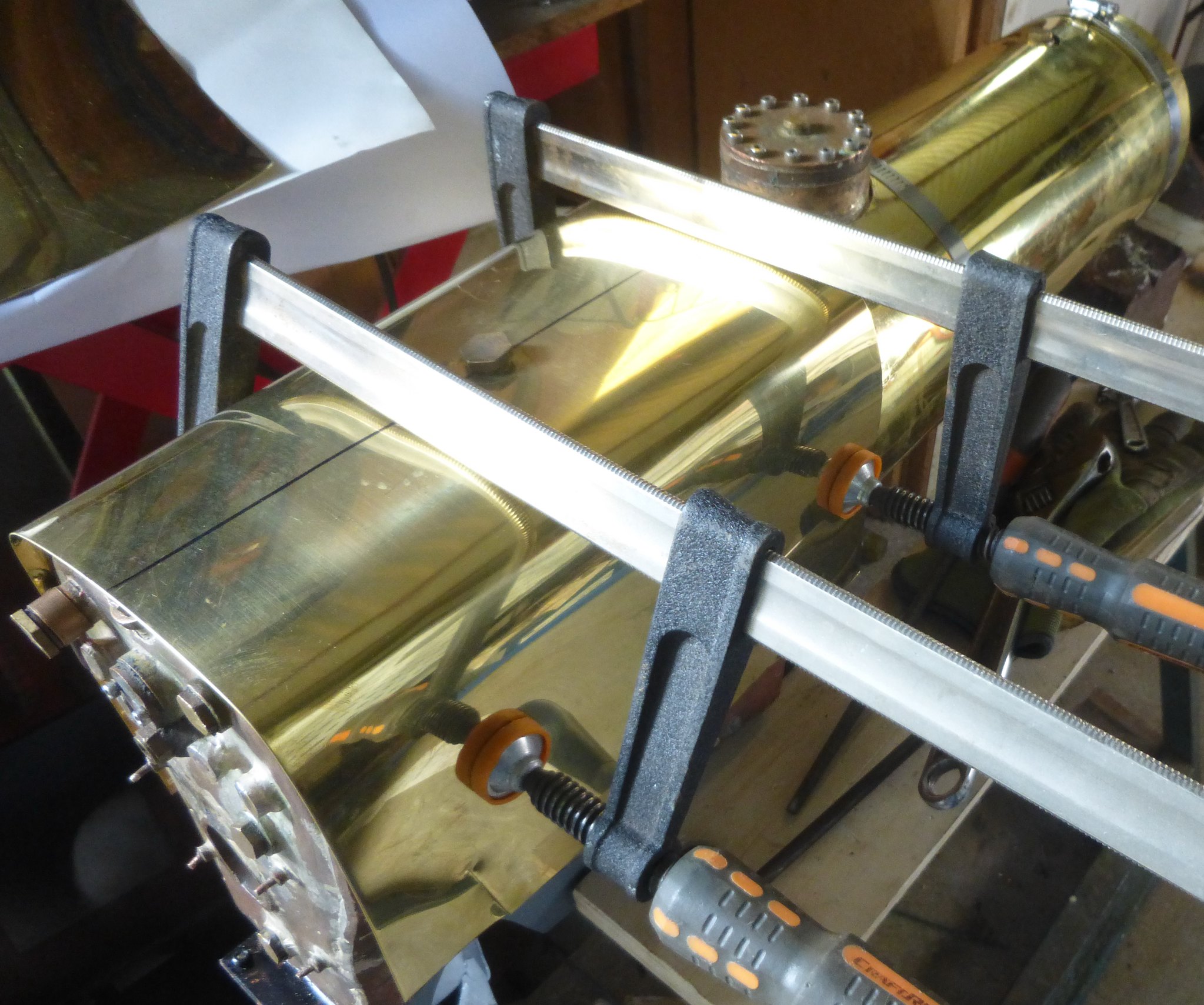 cladding cladding by Brian Leach, on Flickr 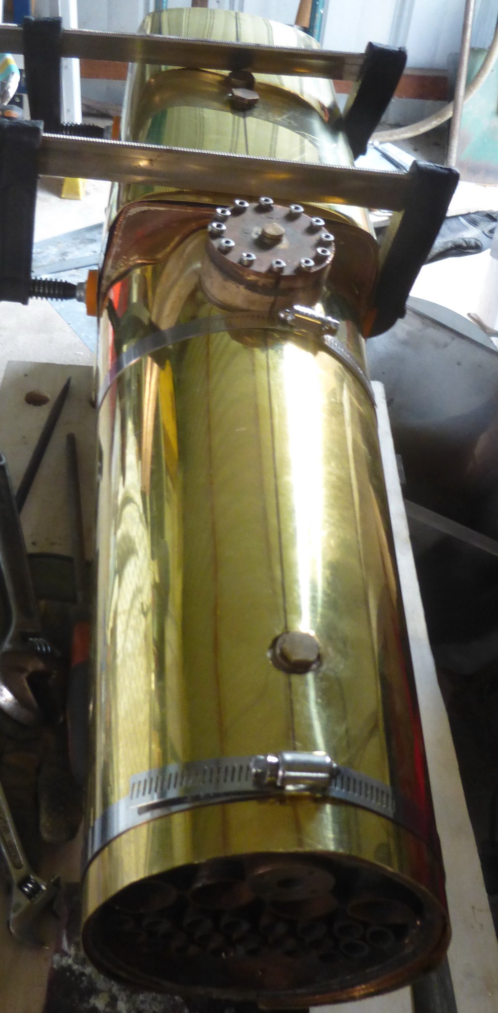 cladding1 cladding1 by Brian Leach, on Flickr So any hints to make this process easier is gratefully received. Brian |
|
|
|
Post by runner42 on Sept 15, 2022 7:25:56 GMT
To close the area where the bolier transitions between the barrel and firebox I have made a transition piece. The principle of the design is to make a number of cuts in the areas where the transition piece is positioned under the barrel and firebox cladding. This is necessary where the circular piece is made and also at places on the firebox to ease bending around a slightly curved surface. A drawing is shown to depict the principle. Brian  Transition Piece Transition Piece by Brian Leach, on Flickr |
|
|
|
Post by runner42 on Sept 16, 2022 6:36:19 GMT
I was hoping for advice on how to finish off the firebox cladding. Whether to affix the firebox cladding to the firebox transition piece and if so how? Also, how to affix the firebox cladding to the boiler firebox. I am still hopeful that someone will provide the how to. Brian 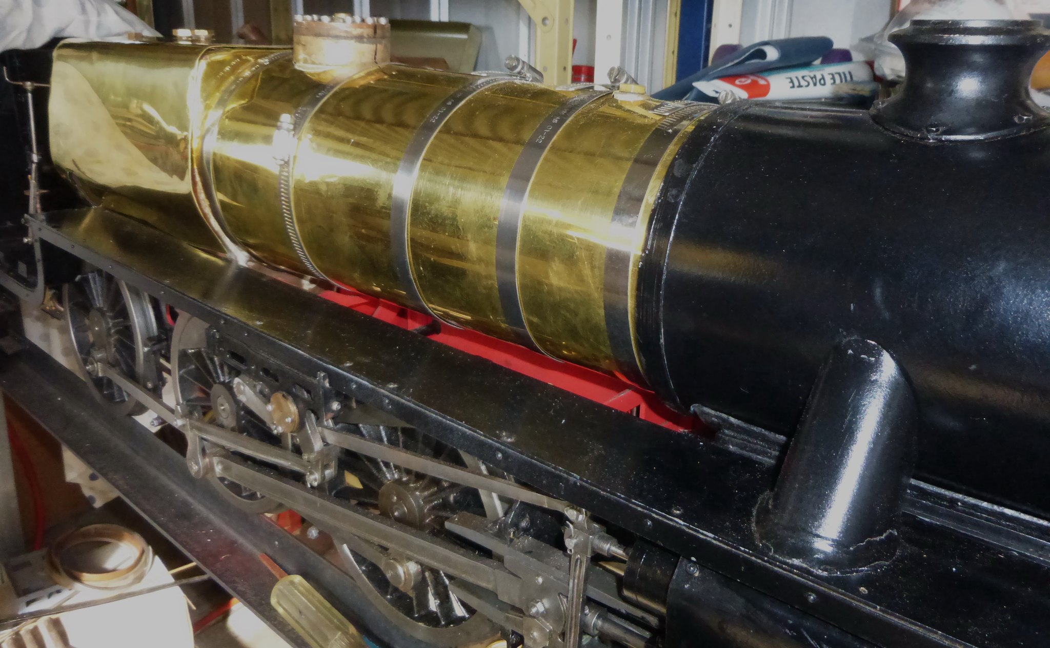 cladding3 cladding3 by Brian Leach, on Flickr  cladding4 cladding4 by Brian Leach, on Flickr |
|
Neale
Part of the e-furniture
 5" Black 5 just started
Posts: 283 
|
Post by Neale on Sept 16, 2022 9:21:24 GMT
No advice from me, I'm afraid, just encouragement to keep posting on progress. I'm a few years behind with my DY Black 5 but following with interest to see the bits that will leap out and bite me in the future! I'm alternately worried and reassured by your reports...
|
|
|
|
Post by Deleted on Sept 16, 2022 10:18:38 GMT
Hi Brian... I can't help with the Black 5 per se but can share how it's done on 4472 which I assume will be similar for most locomotives. Basically, the various shaped sections are held together by short round head slot screws. I don't think that they go into the boiler shell itself..although perhaps on some they may go into the framework beneath. When I get to this stage for 4472 I plan to make the sections a good fit which when all screwed together is self-contained. Here's a picture of 4472's firebox closeup to show the screws employed.  Hope this is of some use... Kind regards Pete |
|
|
|
Post by runner42 on Sept 17, 2022 0:29:42 GMT
Hi Pete,
that is a plan, thanks for that. The only issue is what size of screws would be suitable and would you be able to tap the mating half being only 0.5mm thick? I have 2.5 mm SS screws which are the same thread size of 7BA so I could try this out on a scrap pieces to see if it provides enough thickness to take the thread. If not, perhaps soldering a thin nut to give added thread thickness.
Brian
|
|
|
|
Post by Deleted on Sept 17, 2022 8:17:51 GMT
Hi Brian
I wouldn't use screws that large, not if wanting to be close to scale. As stated I haven't got to this stage yet but would think the screws would be something like 12BA or smaller. I probably wouldn't go smaller than 12 BA though, just to make life a little easier practicable wise. At a glance it looks to me that most sections lap over the throatplate cladding so I'd probably beef that up a liitle with something like a brass strip sweated onto its rear face fot extra thread depth for the screws, alternatively half nuts could be soldered on.
Just some ideas, I may ask some of the guys who work on 4472 for how the real loco is done first, I suspect its similar to what I have just laid out.
Cheers
Pete
|
|
stevep
Elder Statesman
  
Posts: 1,073
|
Post by stevep on Sept 17, 2022 9:07:13 GMT
IIRC, Keith Wilson included quite a lot of details about boiler cleading in one of his ME articles (Bulldog?), and I used his description when I did my Stanier.
Basically, the top of the cleading over the firebox is a flat sheet. The sides are shaped to match the firebox sides, and screw (as Pete (greenlade) has said and illustrated), into extensions fixed to the throatplate (which is shaped to match the throatplate of the boiler) and backhead cleading. I think I put an extension on on the top of my sides, to which the top plate screwed.
The cleading becomes a 'box', of a similar shape to the firebox of the boiler, but a little larger.
|
|
|
|
Post by runner42 on Sept 27, 2022 7:46:39 GMT
I started populating the backhead. Through experience I made all the backhead fittings before starting the boiler, this is to ensure that the bushes when silver soldered to the backhead were correctly placed so that when the applicable fitting was screwed up tight that is was at the correct orientation. This measure didn't last due probably to degradation in the bush thread forms so when they were screwed up tight the orientation was slightly off. So the palliative action was to produce thin nuts that go between the fitting and boiler bush. So everything is now positioned as it should be. Except for the blowdown valve!! The problem is not orientation it is one of determining the exhaust pathway. DY didn't show a backhead mounted blowdown valve, his design calls for a throat mounted everlasting blowdown valve and without further description on the design and positioning of this valve. I imagine that it requires some explanation on the operating mechanism at least. I have a bush in position for the everlasting blowdown valve. No matter my design includes a backhead mounted blowdown valve which is positioned at the bottom of the backhead just above the foundation ring. The exhaust pathway is impeded by the drag box and modification of this is not readily achieved because of the steam operated valve mounted underneath the drag box prevents this. The exhaust pathway will not be straight down but will have to be a circuitous route which reduces the blowdown valves effectiveness.
Perhaps I need some ideas on how to route the exhaust pathway and or more details on the everlasting blowdown valve and how it is operated, I assume at one side of the locomotive adjascent to the throat plate.
This is a major hold on progress unless and until it is corrected.
Brian
|
|
|
|
Post by Jim on Sept 27, 2022 8:19:33 GMT
Hi Brian,
Re the blowdown valve, I bought a very nice version of the Everlasting Blowdown valve that were fitted to quite a few locomptives including the Britannias.
I quickly realised that its locaton above the foundation ring at the front of the fire box would make it impossible to access once the boiler was mounted on the frames. I also had issues with it tending to weep once under pressure.
As a result I blanked of the original bush and opted for a simple screw plug valve mounted as low as possible on the side of the fire box, it also doubles as the filling point for the boiler and is very easily accessed should it need servicing.
Just a thought
Jim
|
|
|
|
Post by runner42 on Sept 28, 2022 8:02:16 GMT
Thanks Jim, A little thought I am able to modify my existing blowdown valve so that the pathway is at right angles instead of straight down and the drainage connection is screwed into the valve and formed to allow dumping through an existing cut out in the drag box. Brian  Blowdown valve Blowdown valve by Brian Leach, on Flickr |
|
|
|
Post by runner42 on Sept 30, 2022 7:26:31 GMT
Some of the backhead fittings in situ. The whistle valve required a 1/4" x 40 TPI for an 1/8" pipe but at the time I only had 5/16" x 32 TPI nuts and tails for a 3/16" pipe. The whistle requires a 3/16" x 40 TPI nut and tail for a 1/8" pipe. So this mismatch required a adapter piece to change from 3/16" pipe to 1/8" pipe. Happenstance this adapter served as a means of securing the pipework to the chassis and provided more easy installation. More failure points but a continous pipe run from the top of the backhead to whistle mounted under the running board would be difficult and unweildy.  backhead backhead by Brian Leach, on Flickr The blowdown valve now provides a greater range of operation from the initial 180 deg, however this maybe counter productive because the screw type valve is not captive so to go too far may result in screw being blow out of the valve body with catastrophic results. May need some rework.  blowdown valve1 blowdown valve1 by Brian Leach, on Flickr Brian |
|
|
|
Post by runner42 on Oct 23, 2022 4:56:26 GMT
After much deliberation on how to secure the cladding transition piece to the firebox cladding I decided to use solder. This was not entirely sucessful due to small gaps in the transition piece which I covered up with a filler. The spectacle plate in the cab structure had to be reworked again to accomodate the cladding adding extra material to the firebox profile. Although the cab has been installed using the initial fixing points it appears that the atitude of the cab doesn't align with the atitude of the tender. It may be that the springing on one side of the locomotive is vastly different from the other and the weight of the boiler has caused this tilt away from the vertical. Something I will investigate. Brian 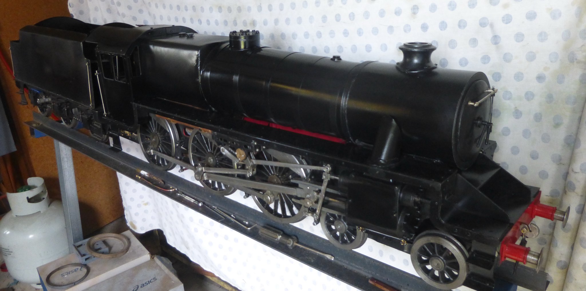 Black 5 Black 5 by Brian Leach, on Flickr  Black 5_1 Black 5_1 by Brian Leach, on Flickr |
|
|
|
Post by runner42 on Oct 24, 2022 3:25:55 GMT
Problem solved. In the first photo of the last post you will notice that the rear upright strut of the handling frame is not vertical. The fixing bolt and nut had come loose allowing the strut to move from the vertical thus causing the rails to twist. The tender was on this twisted section and was also not vertical to the ground plane, whereas the front section was vertical. The result was this difference in the orientation of the tender and locomotive. Pulling the rear strut vertical and tightening the nut and bolt corrected this.
Brian
|
|
Neale
Part of the e-furniture
 5" Black 5 just started
Posts: 283 
|
Post by Neale on Oct 25, 2022 10:15:16 GMT
I can hear the sigh of relief from here!
|
|
|
|
Post by runner42 on Oct 30, 2022 5:03:19 GMT
The next problem is the steam dome cover. The casting I obtained for this was not produced for the Black 5 and the boiler code required a larger steam dome, the result is that the casting could not be machined internally to enable the casting to sit down on the boiler. I tried to machine the casting but it broke through, so I had to fabricate one from 3 mm copper sheet. The fabrication was in 3 sections silver soldered together. The lower section is an annulus shaped to follow the contours of the boiler, the middle section is a tubular form with a shaped edge to match the lower section, the top section is a circular plate that was formed with curved sides to represent the dome. The result is a fair representation of a steam dome cover but somewhat over sized. I shall add some filler between the bottom and middle sections to represent the curved transition normally expected with castings. In practice I could have made the steam dome cover 3/16" lower but I had already committed to the measurement for the middle section so I erred on caution and left it alone. The photo shows the casting and fabricated steam dome. 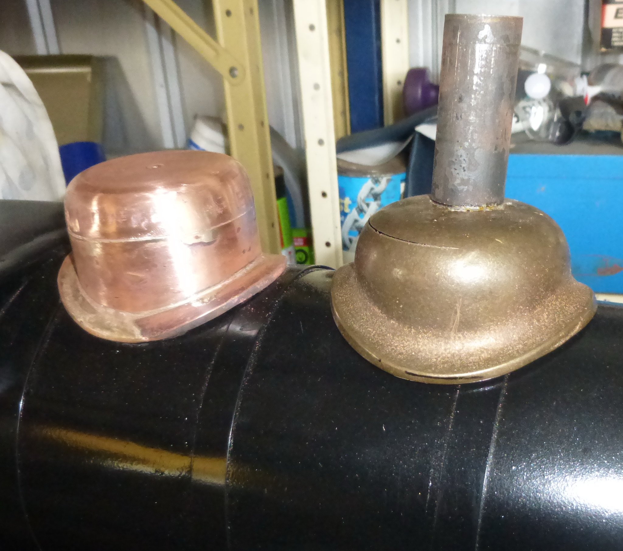 Steam dome cover Steam dome cover by Brian Leach, on Flickr The fabricated steam dome. I remember from my apprenticeship in a R.E.M.E. Depot that during my first year was spent in the Apprentice Traing School where the instructor would often say "highly polished but highly scratched", which can be attributable to my effort. More work neccesary. Brian |
|
|
|
Post by runner42 on Nov 4, 2022 6:43:15 GMT
The top feed casing has given me a bit of a problem. The drawing of the top feed casing appears to be lacking a third projection, ie the plan details are missing. I have shown the composite drawing of the top feed fitting and top feed casing. The connections to the top feed fitting is by 5/16" x 40 TPI so the nut required to interface the pipe is 3/8" across the flats. The top feed casing I assume requires holes to allow the pipes to interface with the top feed fitting, these are not shown. Also is the top feed casing just a cover that drops over the top feed fitting with the pipes already connected, or is as I have made a fitting that needs to be in place before the pipes are connected? The problem with my solution is that the nuts require a specially made spanner to completely make the connection. Even so I cannot gaurantee that I have connected them as tight as a steam connection requires.  top feed and casing top feed and casing by Brian Leach, on Flickr 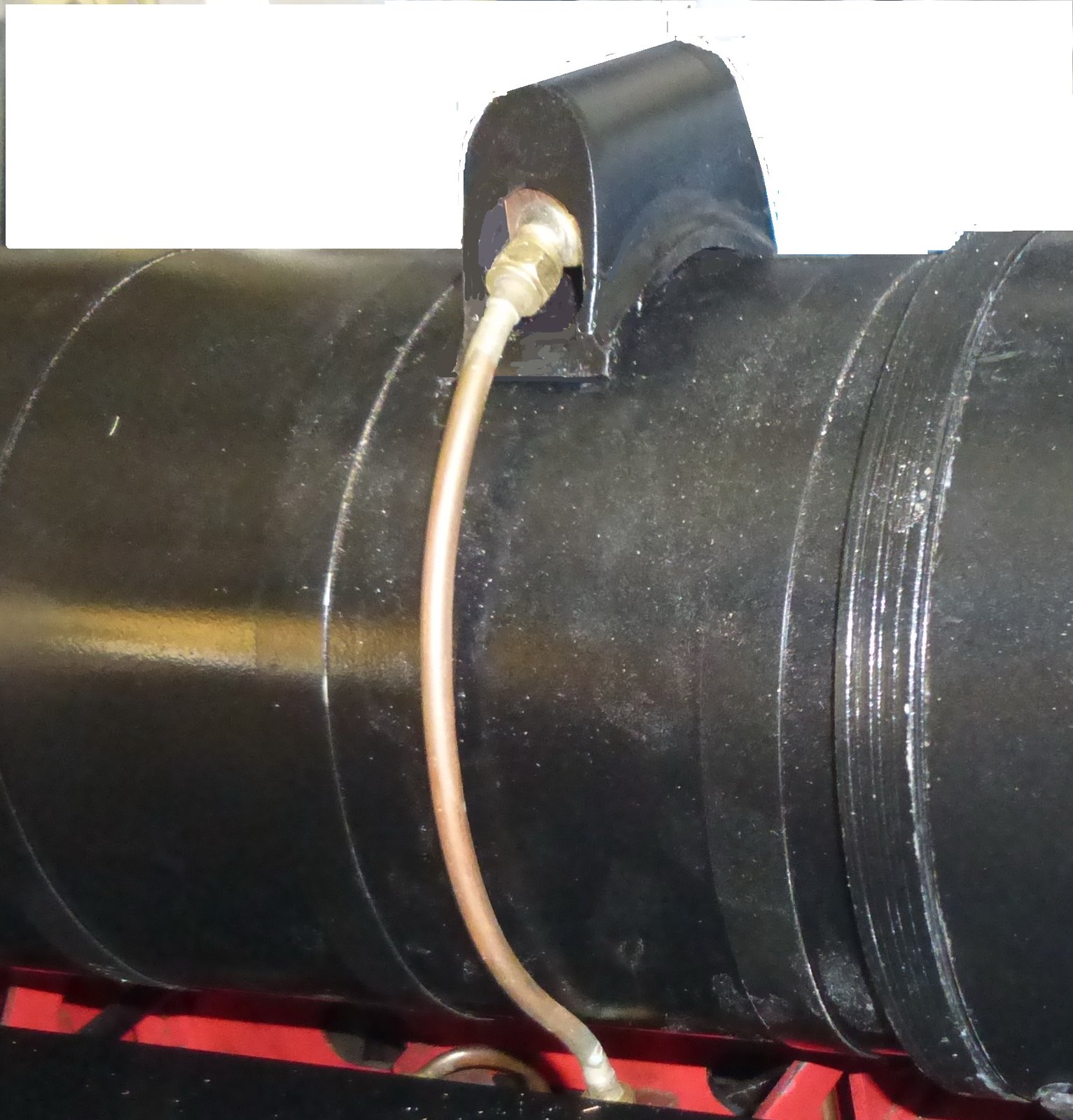 Top Feed Casing1 Top Feed Casing1 by Brian Leach, on Flickr Any help in solving this problem is welcomed. Brian |
|
44767
Statesman
 
Posts: 539
|
Post by 44767 on Nov 6, 2022 3:33:29 GMT
I purchased the top feed casing casting from Don in 1991. It needs work to make it fit, as you'd expect. To answer your query, the bottom is open and the whole cover merely sits over the pipework and clacks once the pipes are tightened.   I hope this helps. Mike |
|
oldnorton
Statesman
  5" gauge LMS enthusiast
Posts: 725
Member is Online
|
Post by oldnorton on Nov 6, 2022 11:08:07 GMT
Hello Brian You will not get it to look exactly like the prototype because they had the feed pipes set into the boiler cleading. The cover is just a sheet metal fabrication, just like you have now. You might be able to put some side covers on it to hide the nuts, and cut slots so that you can just slip the cover over? This picture Mike will also enjoy  I took it in 2014 at the North Norfolk Railway when it was running with 45305. Norm  |
|