|
|
Post by runner42 on Nov 6, 2022 22:37:52 GMT
Thanks Mike and Norm.
Mike have you pictures of the casting in situ? It requires I assume that apertures are needed for the pipes to be able to be connected and it may run into the same situation that I experienced that the 3/8" nut would be difficult to do up, unless the cover is just machined in a way that it can be dropped over after the pipes have been connected. This would require that the centres of the ends would needed to be removed.
Norm, I assume that you haven't reached that point in your build, otherwise you would have provided your solution. Any ideas on how you intend to address this issue?
Brian
|
|
oldnorton
Statesman
  5" gauge LMS enthusiast
Posts: 724
|
Post by oldnorton on Nov 7, 2022 14:18:22 GMT
Norm, I assume that you haven't reached that point in your build, otherwise you would have provided your solution. Any ideas on how you intend to address this issue? You are right, not there yet, but the good news is that I have just restarted my Black 5 build, after switching away from it to the Britannia about three years ago  For the Black 5 I will screw in the top feed manifold to the boiler, set the feed pipes below the cleading surface and tighten those into the manifold, then make a steel or brass fabricated top feed cover and bolt that down to the boiler cleading. The feed pipe cover strips will be similarly bolted with small head (12BA) screws. I do have a casting just like the one in Mike's picture, but probably will not use it, and it's your choice whether to use one or keep with a fabricated cover. Your quickest and simplest solution might be to beat out some thin brass or copper end covers (the 'knuckle' shaped bits on the side) and solder these onto your existing cover. Cut slits each side to enable it to fit over the two pipes. You just need some internal spring arrangement to let you clip or push-fit it onto the manifold. Norm |
|
|
|
Post by Deleted on Nov 19, 2022 20:54:06 GMT
Hey everyone. I am looking for my next project and this is of interest to me. If I go ahead with it I intend to get drawings and castings from Reeves. I built Days A3 tender and found his drawings to be excellent. Are there any significant errors in the Black 5 drawings. Cheers
|
|
44767
Statesman
 
Posts: 539
|
Post by 44767 on Nov 19, 2022 23:57:15 GMT
Hey everyone. I am looking for my next project and this is of interest to me. If I go ahead with it I intend to get drawings and castings from Reeves. I built Days A3 tender and found his drawings to be excellent. Are there any significant errors in the Black 5 drawings. Cheers There are a few minor errors but most of them you'll realise having studied the drawing. Perhaps one which you may not see at first is the front tender stretcher needs clearance for the front tender wheels. All-in-all, it's a good design but most of the detail is up to the builder to research and make on his own as the drawing is light on detail. There are a few on here who can help you out if you chose to make a start on this model. Cheers,Mike |
|
|
|
Post by richb on Dec 12, 2022 19:04:50 GMT
Hi
I am also building a Don Young Black 5 and I am about to fix the balance weights to the driving wheels. Don only shows the left hand view of the engine and the left hand wheel has the weight rotated slightly clockwise around the spokes if the crankpin was at the 6 o'clock position. Is the right hand wheel the same as the left, with the weight rotated one spoke clockwise with the pin at the bottom? I hope someone who has built a Black 5 or has some knowledge of steam locos could let me know.
Thanks
Rich
|
|
oldnorton
Statesman
  5" gauge LMS enthusiast
Posts: 724
|
Post by oldnorton on Dec 13, 2022 10:00:35 GMT
Hi Rich
We shouldn't really fill Brian's build thread with our third party chat, but I guess he won't mind a quick reply.
The Driving Wheel plate offset is the same direction on both left and right, so the two wheels laid on a bench look the same. This seems a bit illogical if you consider the static balance of one side at a time, but it is done to help balance the dynamic effect of the 90deg cranks.
I worked out the static balancing effect of the two plates on each wheel for my 5" Black Five, against the mass of the coupling and connecting rods. It does not need any additional lead poured between the plates. I used some epoxy to fill the gap and give a decorative top.
If you have any more comment just start a new thread and I am sure others might appreciate joining in.
Norm
|
|
44767
Statesman
 
Posts: 539
|
Post by 44767 on Dec 14, 2022 9:16:44 GMT
I think that with the very general title to this thread, it can attract any comment to do with Don's design for the Black 5. It would help anyone who is searching for information about this model to find it all in one place rather than only comments by the thread's initial author with the need to find piecemeal information elswhere. I don't think the intention was only to follow runner42's build.
Mike
|
|
|
|
Post by richb on Dec 14, 2022 17:11:38 GMT
An even quicker reply then. Ok thanks for that.
|
|
|
|
Post by runner42 on Dec 16, 2022 5:58:25 GMT
I had a productive day in the shed today, although I had to have an early minute because my upper back gets an ache between the shoulder blades when I stand for too long. The ache goes away when I sit down. I think it is muscular rather than a spinal problem, but just in case the Doctor has recomended an X ray. My posture is that of an 81 yo a bit slouchy and round shoulders. I probably need to strengthen muscles in my upper back to compensate for the bench presses I do at the gym which strengthens the chest muscles. This imbalance in muscle strength causes the head to protrude forward and putting strain on the back. Enough of that aspect, back to ME.
I individually pressure tested all the bits that hang off the boiler, the regulator, blower valve and tube, superheater with wet and dry headers, the top feed assembly, manifold with the injector steam valve and steam brake take off. I had to redesign the manifold to remove the whistle valve from it's position on the far RH side to a better ergonomic position facing forward. It was too cramped in the position chosen by DY on my build.
Brian
|
|
|
|
Post by Deleted on Dec 24, 2022 1:22:01 GMT
I'm also working on Black 5 tender springs. I'm building the DY design for the chassis - in effect, everything below the tank - but also have the "Galatea" drawings by Allcock which are said to be a more detailed version. Which is great if you can read the very cluttered drawings! However, the Galatea spring design is well-drawn with individual leaf lengths given. Happy to pass on a PDF extract of the relevant bits (PM me). Problem is that the design is for 1.2mm tufnol leaves which might have been available once but now it seems to be a choice of 1mm or 2mm. I have bought a 600x600 sheet as the engine uses something similar as well. I'm planning to make a sample spring to drawing (ignoring difference in material thickness for now) and just see how it goes. I also have some annealed spring steel (thinner than the tufnol) and my plan is to stiffen the spring with some of that, suitably machined then tempered, as I suspect that the tufnol alone is going to be too weak. The idea is that I can CNC cut a set of spring leaves to drawing from the tufnol sheet. I'm also working on trying to figure out how to assemble the body/tank assembly from a laser-cut kit. That's not entirely intuitive either! However, I'm swapping between the two tasks depending on which I find least frustrating at any given moment... Hi Neale, I hope I am not late to the party. A friend of mine has a spring calculator for leaf springs and we have just redone the leaf springs for Galatea. |
|
|
|
Post by runner42 on Jan 3, 2023 6:12:19 GMT
I am required to put the club's assigned ser no on my boiler. The BI has advised that a plate carrying the ser no cannot be soft solder to the boiler it must be silver soldered. This has caused me some consternation because no futher silver solsering can be undertaken on a finished boiler. So I have decided to stamp the ser no using numbered and lettered punches and because of need to have it in an easily readable I have decided to place the ser no on the steam dome where the material thickness is substantial and can be accessed by just lifting the steam dome cover.
I am currently making the support beams to affix to the ash pan which holds the grate in place. The grate is constructed in three parts left centre and right hand which is presumeably to enable the three sections to be removed through the fire hole door. I am not there yet to demonstrate to myself that this can removed and replaced, but notwithstanding that this can be done what special tools are needed to effect this operation. Is anyone reached this point and give me details on how it is undertaken?
Brian
|
|
|
|
Post by flyingfox on Jan 3, 2023 7:43:49 GMT
Greetings Brian, the dome ring is a good place to stamp the number, the idea is that it needs to be fixed to a solid piece of the boiler which would be straightforward to find after a catastrophe. It is also a good place because it is easily seen, whereas, I have found, many numbers, stamped on the foundation ring require serious dismantling of the footplate or cleading to be seen.
Re the grate, mine are mostly 71/4 gauge, inserted via the firehole, and I have made a simple hooks to lift the sections in and out. A pair of cheap, long nosed bent end pliars are also useful.
Most important is a good torch so you can see what you are doing.
Regards
Another Brian
|
|
|
|
Post by runner42 on Jan 16, 2023 4:07:12 GMT
Having assembled the locomotive completely (almost), I realised that the cleading cladding has to be removed because the provision for the handrail stantions have to have some means for screwing the stantions in place. Nearly everything has to be removed, the boiler from the chassis etc. Because some pads have to be soldered in place to the 1/2 mm brass sheet the paint has to be removed from the brass sheet so it's a complete cock up on my part not to have realised this omission sooner.
Brian
|
|
weary
Part of the e-furniture

Posts: 302
|
Post by weary on Jan 16, 2023 8:46:22 GMT
Glue the handrail knob securing pads to the cladding this avoiding heat & (repair) repaint??
Phil
|
|
|
|
Post by David on Jan 16, 2023 11:13:26 GMT
I know those types of own goal very well Brian!
I've also just had the same problem with the boiler number. I went to paint the dummy backhead and realised we never assigned a number to the boiler a couple of years ago (the BI knowing how long I'll take to finish the loco). Luckily I was given the same solution so I could go ahead with the painting rather than disassembling the entire steam tight backhead and making a mess of the cutout and risking a silver solder job.
It sounds like you're really getting on with it.
|
|
|
|
Post by runner42 on Feb 9, 2023 0:44:33 GMT
Before I can say task completed Ii need to give some thought to how I can access all the points that requires oiling.The main concern is the man bearings on the coupled wheels. Access appears tight with the boiler in position so some remote feed system is required. Any ideas?
Brian
|
|
|
|
Post by David on Feb 9, 2023 2:11:10 GMT
Is it too late to drill an axial hole into the end of the axles and then a cross hole so oil can be squirted in that way? I 'retrofitted' that system to the front coupled wheels on my 0-4-0. I would have done the rear axle too except I didn't want to disturb the eccentrics which seemed like it would be necessary.
|
|
|
|
Post by runner42 on Feb 9, 2023 5:33:40 GMT
Is it too late to drill an axial hole into the end of the axles and then a cross hole so oil can be squirted in that way? I 'retrofitted' that system to the front coupled wheels on my 0-4-0. I would have done the rear axle too except I didn't want to disturb the eccentrics which seemed like it would be necessary. David, yes too late. Don Young doesn't appear to have addressed this issue for the Black 5 and generally is maintenance issues given by any locomotive designer or is it up to the individual builder to sort it out for themselves? Looking at my particular problem it doesn't appear too difficult to use a pump operated oil can with a long thin feed tube applied between the frame and boiler to provide oil to the opposite side bearings. This is OK for the front and middle coupled wheels but impratical for the trailing wheel set because the firebox and ashpan prevent access. Brian |
|
|
|
Post by dhamblin on Feb 9, 2023 7:36:11 GMT
How big is the wheel boss - does it prevent seeing the axlebox top face when wheel rotated to have rods down? Also does the valance beneath the cab get it the way? Usually there is enough room to get an oil can thin pipe in between the spokes.
Regards,
Dan
|
|
|
|
Post by runner42 on Feb 10, 2023 3:52:41 GMT
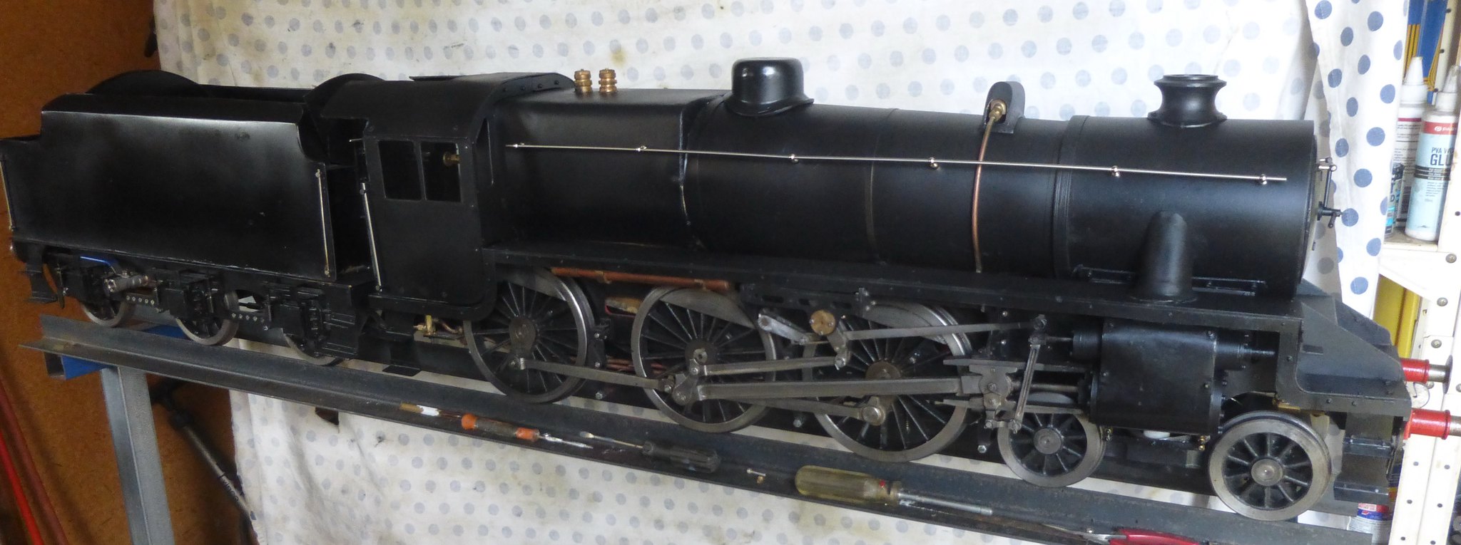
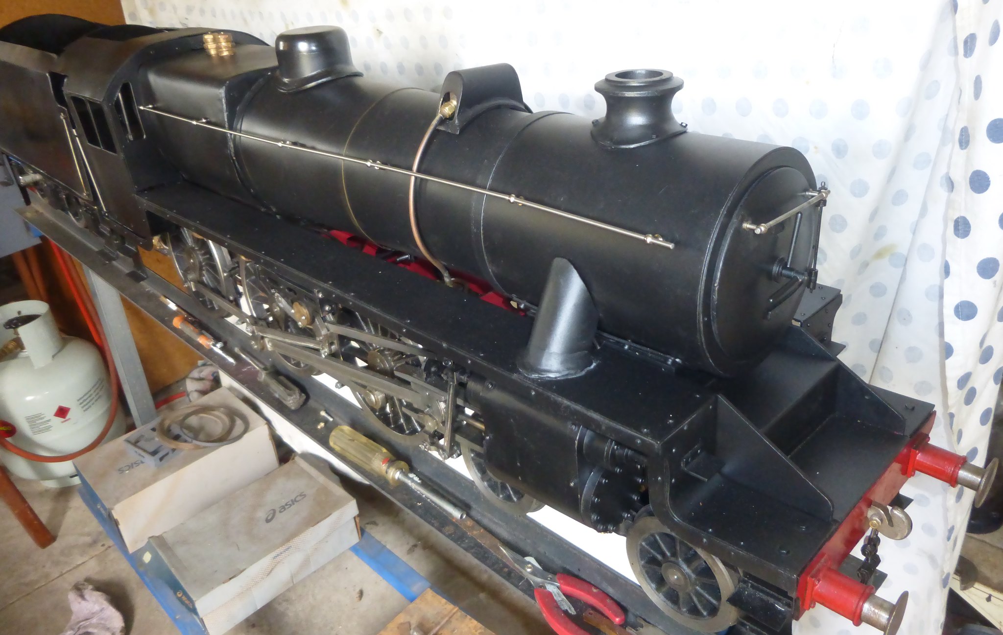
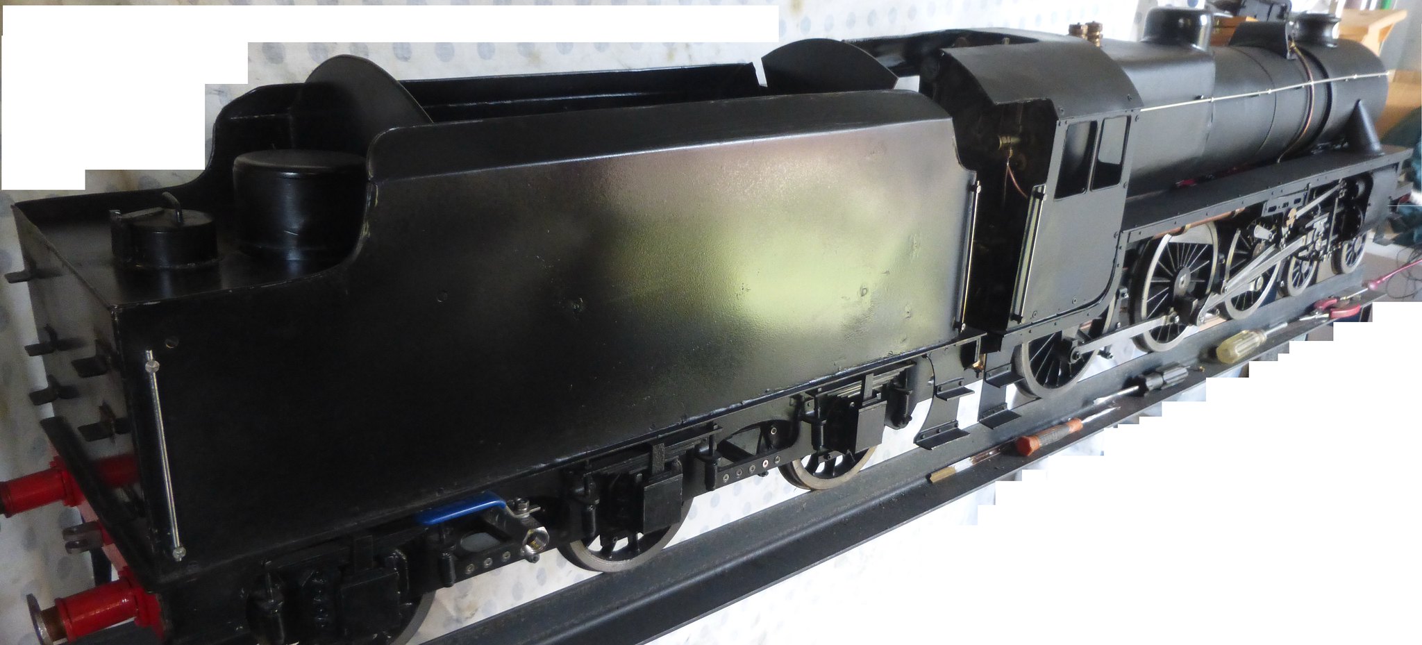
Everything is assembled apart from the grate. DY didn't specify where the cross beams in the ashpan should be placed to support the 3 piece grate, I put the forward one as clost to the end as possible which makes installing the grate difficult. After attempts through the fire door to place the 3 pieces failed due to being unable to reach the foreward most cross beam causing the 3 piece grate to drop into the ashpan, I realise that the foreward most cross beam needs to be moved back so that the grate can be more readily be placed without falling into the ashpan. This requires removal of the boiler from the chassis which is not a straightforwatd task. sh*t happens! The assembled locomotive. The paint is so easily marked and or scratched that it requires a touch up after final assembly.  Black 5_2 Black 5_2 by Brian Leach, on Flickr  Black 5_4 Black 5_4 by Brian Leach, on Flickr  Black 5_6 Black 5_6 by Brian Leach, on Flickr The backhead populated except the steam operated brakes. A colleague said that brakes on the locomotive is not necessary since the braking is done on the driver's truck.  Black 5_9 Black 5_9 by Brian Leach, on Flickr Brian |
|