barlowworks
Statesman
  Now finished my other projects, Britannia here I come
Posts: 878 
|
Post by barlowworks on Jan 5, 2021 10:02:55 GMT
Unfortunately, spinning is a black art that has eluded me also. I did have a go at spinning the dome for my Britannia in brass and in copper but only succeeded in making a slightly domed frilly petticoat. I eventually stumped up the cash for a big lump of brass and turned it up on the lathe.
Mike
|
|
|
|
Post by 92220 on Jan 5, 2021 10:35:09 GMT
Hi Mike.
The dome on the Britannia is easier to press. If you make a metal model of the dome, smaller by approx the thickness of the metal, and get hold of some pieces of 1/4" thick rubber, around 60 or 70 Shore, these can be laid on top of each other to make a thickness of 1". This can then be fitted inside a metal box to stop it expanding sideways when pressed. The metal sheet is then placed on top of the rubber, and the press tool forced down. The rubber holds the metal firmly against the form tool because it cannot expand away sideways....only upwards around the form tool. Ideally a flypress is best because when using rubber form supports, a quick, punch is better than a slow press. Because your dome is relatively shallow (like the 9F) it should form in this way, very easily. Brass, copper or even, possibly, steel. 22swg should be easy to form, and still be relatively strong. It might even be possible to get a decent strong pressing from 24swg.
Bob.
|
|
|
|
Post by gwr14xx on Jan 5, 2021 10:55:54 GMT
When I got my Winson 9f, I wanted a dome that looked more authentic, so formed one from 24g copper sheet. A female pattern was carved from a block of beech, the annealed copper sheet laid on it and clamped at each side. It was then easy to chase the copper sheet down into the pattern, and then trim to shape. As the original Winson dome was held down by a central screw, I reinforced the top of the new dome by comsoling an 18g brass disc inside the top before drilling and countersinking the hole for the fixing screw. I now have an authentic looking dome that is easy to remove should I need to get to the regulator.
Regards,
Eddie.
|
|
|
|
Post by delaplume on Jan 5, 2021 12:07:45 GMT
At the risk of getting shot by the righteous Brothers}----You could always approach HM Gov.---they usually have plenty of "Spin Doctors" to hand --------LoL !!
Sorry Adam--- let's get back to your CoT 3440..
|
|
Gary L
Elder Statesman
  
Posts: 1,208
|
Post by Gary L on Jan 5, 2021 12:59:57 GMT
Hi Gary, It's not leverage of the tool that is the problem, it is driving the workpiece against the drag of the tool. Some books suggest applying pressure from a pad in the tailstock, but I found the workpiece just slipped. I have spun things successfully when there was the possibility of having substantial driving pegs through the workpiece, but if they were too small they simply tore the metal. Maybe I was doing something wrong.... Malcolm Hi Malcolm It depends on the size of the spinning and the thickness of material. I don't think I would try to spin a boiler tubeplate for example! But for smaller components, like cylinder end covers and safety valve bonnets in thin material there shouldn't be a problem. These tender 'trumpets' probably fall about half-way, because the bend is quite tight and the material on the thick side. My lathe has a cogged belt drive, so handles torque reasonably well; I couldn't comment about Vee-belts but I take the point. The workholding requires a quickly-releasable fixing, because of the need to anneal frequently, which indicates a clamping method, using the tailstock. However if you don't have a 'live' centre (with ball-bearings) the more pressure you exert, the more friction that your drive has to overcome, and probably a lot of heat too. It can be done (I did some Speedy cylinder end caps this way) but it isn't ideal. I didn't want to invest in a special 'live' spinning tailstock device (they do exist) for the small amount I do, but I do have a heavy duty live centre, with a point. So I turned up a wooden disc, about 1" thick, and then bored a 60 degree recess to fit the live centre. Interpose this disc between the job and the tailstock, and you can wind in the tailstock as tight as you like; the bearings take the strain and the work is firmly clamped. At the headstock end, it is just your former, typically also wooden, screwed to a faceplate. Clamped between the two wooden pieces, I don't have any troubles with driving the blank. Hope this helps a bit Gary |
|
mbrown
Elder Statesman
  
Posts: 1,790
|
Post by mbrown on Jan 5, 2021 13:08:52 GMT
Thanks Gary. I tried that tailstock and live centre method, but my bell was a deep "goblet" shape so I was probably trying for too much deformation. The flat area at the top was also very small so there wasn't much to clamp against.
Before lockdown, I was actually reduced to searching junk shops to see if I could find a small metal goblet of the right size - I found several that would have made a superb bell for a 7.25"g version!
Malcolm
|
|
Gary L
Elder Statesman
  
Posts: 1,208
|
Post by Gary L on Jan 5, 2021 14:16:23 GMT
Thanks Gary. I tried that tailstock and live centre method, but my bell was a deep "goblet" shape so I was probably trying for too much deformation. The flat area at the top was also very small so there wasn't much to clamp against. Before lockdown, I was actually reduced to searching junk shops to see if I could find a small metal goblet of the right size - I found several that would have made a superb bell for a 7.25"g version! Malcolm I think the small clamping area was probably the main problem Malcolm. I don't think the depth of the deformation required is an issue on its own, but in my simple terms I'd look at this way. Spinning is a stretching process. If you start at the base of your goblet, the metal will be substantially thinner when you get to the rim. Assuming you anneal regularly (!) the spinning will also get easier as you approach the rim. So it is the early stages that require the most effort, because the metal is proportionately thicker and the stretching round the initial bend is more severe. For a given rim thickness, the deeper the spinning, the thicker the blank needs to be, and this is where difficulties can arise. I've no idea how you would calculate it, I think it is down to trial and error. Mike (Barlowworks) talks about 'frilly petticoats'. We've all been there Mike! It happens if you stop stretching the metal and try to compress it to shape instead, which doesn' t work; or it doesn't for beginners like me. The correct technique is almost like a potter raising a jug from a dollop of clay, you sort of 'sweep' the metal with the tool towards the headstock, and in the process it pulls itself inwards into the former. The metal grips the former tightly too; if there is a cylindrical section involved, it is a good idea to include a small amount of 'draw' in the former. Gary |
|
mbrown
Elder Statesman
  
Posts: 1,790
|
Post by mbrown on Jan 5, 2021 14:57:56 GMT
You're probably right that it is time to let Adam have his thread back - I'd only note that my successful attempts at spinning have been just as you say. Like the safety valve base for the Burma Mines loco, resembling a shallow top hat, which seemed to go nowhere after several anneallings and then suddenly seemed to flow like plasticine when it reached a critical point around the first curve. But for that one I had two substantial pegs as drivers, so keeping the plate moving was no problem.
Malcolm
|
|
|
|
Post by Cro on Jan 6, 2021 12:34:35 GMT
I spent yesterday working on the water valves, I have also drawn up the handles, brackets and lifting links to be cast with a few other bits. These valves are really simple PTFE style but I have made the gland/seals in the same way I did my BR Gresham & Craven water valves but to keep it simple the "stuffing gland" is just a thumb nut which screws against a shoulder nipping the o-rings. All simple turning jobs in brass, the main body I ground up a new boring tool from an old slot mill to keep it nice and rigid and get a good parallel bore.  Untitled Untitled by Adam Cro, on Flickr The spindle drive is via a hexagon pocket, I cheated and rather than try turn 6.5 Length from 3/16" to an 1/8" or machine the hex I used some brass hex I had at 5mm which was close enough and soldered this to the end of the rod.  Untitled Untitled by Adam Cro, on Flickr Leaving a slightly sharp edge on the bottom helps these cut the pocket in the PTFE which has a hole drilled 4.9mm.  Untitled Untitled by Adam Cro, on Flickr  Untitled Untitled by Adam Cro, on Flickr The large o-ring seals the cap onto the body and the smaller one around the shaft.  Untitled Untitled by Adam Cro, on Flickr The other end of the spindle has a .08" square with a 12ba hole tapped in it to take the bolt and washer that will retain the handle.  Untitled Untitled by Adam Cro, on Flickr Onto fitting of the toolboxes now and working on the rear end, dome and filler cap - oh no not more hinges!! Adam |
|
|
|
Post by Cro on Jan 9, 2021 18:37:53 GMT
Evening All! Well thats it for now, the City's tender is reunited with the loco back in the office whilst I get back onto other work. On Monday I start a new job designing parts for classic cars and also designing race gearboxes and engines, a new challenge for me I know nothing about cars so its a different from high temperature vacuum heating, and I wanted to get the City back to the office before starting. So here is the last update finishing off the filler cap, mounting the dome and clean up. Seeing as I forgot to take photos of the last hinges, here are the parts to make up the filler cap ones prior to soldering. As before, turned tubes with 0.8mm holes using PCB drills parted off overlength. These are silver soldered prior to putting in the slots.  Untitled Untitled by Adam Cro, on Flickr Again the rivet holes are 1.1mm for 1/32" rivets (0.81mm) so they were located on the tube and aligned with the pin before soft soldering.  Untitled Untitled by Adam Cro, on Flickr The straps should be on the top of the lid but the way the parts were designed/made meant that this was never going to work, inside the lid sits a bit high at the back but its good enough.  Untitled Untitled by Adam Cro, on Flickr For the dome I had a place called Spin360 I found on Facebook Spin one, well 3 actually in case I messed it up. I then split this very simply with a hacksaw after some careful marking out. I spoke with Roger about this hoping he would offer an elegant but simple solution to use a slitting saw and he simply said "use a hacksaw!" so I did.  Untitled Untitled by Adam Cro, on Flickr Once split I made a base for the rear portion and soft soldered them together so this could be fitted the rear removable section and profiling to fit the detail plate I have fitted seen on the current CoT tender. No idea its purpose but easy enough to add. The smaller section within the coal space will get soft soldered on when I do the last heat up.  Untitled Untitled by Adam Cro, on Flickr 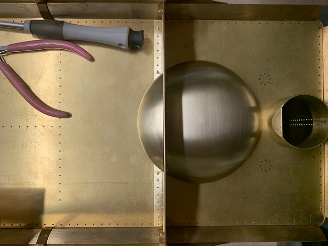 Untitled Untitled by Adam Cro, on Flickr Last up the filler tube was soldered to the plate and the detail rivets squeezed in. This caused a minor headache in turning the plate banana shape. In the end I left it in the fan oven on Max for an hour and eventually had to cut a section out to relieve the stress and after some tweaking its flat again.  Untitled Untitled by Adam Cro, on Flickr Final job before it left the workshop was to add one of the tender plates that I got with the loco, expertly made by Diane Carney many moons ago I imagine. 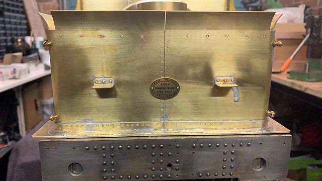 Untitled Untitled by Adam Cro, on Flickr And here she is back where I can admire her whilst working away in the evenings.  Untitled Untitled by Adam Cro, on Flickr When the castings arrive I'll schedule in time to do the following: Fit water valves and handles Fit water level gauge (should I try make it work....?) Beading (I hope to make a jig to drill and rivet this in place) Lamp irons Front hand rails And then the final solder up and clean up around the tank. Not much to do, mostly little things. There will be some boxes to make up around the injector spindles and a false floor in the coal space but they can wait till late on when the footplate height is established. Back to making up fittings now, Thanks for all the support on this over the last couple of weeks glad people have enjoyed it - Boiler is the next big step when the kit arrives. Adam |
|
|
|
Post by Cro on Mar 19, 2021 11:19:50 GMT
Just a little update after the casting delivery earlier in the week. For those that don't follow my facebook page I am currently on house arrest and locked out of the workshop due to having an Epileptic Seize 2 weeks ago. This is the first I've had in 10 years so a bit of a shock but means I can't drive for now, potentially 12 months, and really shouldn't be in the workshop alone around a lathe and so on so progress on pretty much everything may be a bit slower than normal. That said I managed 5 minutes last night with Jess keeping an eye on me and I decided just to skim the bottom of the water gauge fitting and fit the injector water valve handles and see how it all looked on the tank. Just a few photos to show the bits in situ really. I really want to get on and finish the tank now the bits have arrived but between taking it slow, working on the house when the builders have finished C*&king it up and work I'm not sure when I'll get round to it. I showed the lifting links in my fittings thread but here it is again to keep it all together.  Untitled Untitled by Adam Cro, on Flickr The water gauge after a little clean up.  Untitled Untitled by Adam Cro, on Flickr And in place - this was mainly possible thanks to some photos from another forum member Brian.  Untitled Untitled by Adam Cro, on Flickr  Picture 127 Picture 127 by Adam Cro, on Flickr Injector Water Valve handles and brackets.  Untitled Untitled by Adam Cro, on Flickr  Untitled Untitled by Adam Cro, on Flickr For comparison. 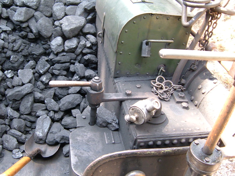 Picture 128 Picture 128 by Adam Cro, on Flickr Right, back to work before hopefully more DIY under strict supervision later on. Thanks all, Adam |
|
|
|
Post by 92220 on Mar 23, 2021 19:09:32 GMT
Hi Adam. Another way of making the flares is to use a piece of brass tube of the right thickness and press a shaped plunger into it. It would be relatively easy to make up a press tool. You could turn up a punch the correct shape for the INSIDE, then find a piece of hardish thick walled rubber tube that tightly fits around the smaller diameter. That should then be fitted inside another piece of steel tube to support it. The brass tube is then placed inside the rubber tube and the shaped plunger pressed in to depth. You should end up with an exact shaped flared brass tube that can then be cut in quarters. I forgot to say that the outer steel support tube needs to have an integral bottom, to stop the brass tube being pushed on through by the form tool. You may need to try a couple of different rubber tubes to find the best rigidity, but harder rubber is better than softer, to make sure the brass tube forms properly. The rubber will want to expand sideways when the form tool is pressed into the brass tube, but the outer steel case stops it expanding sideways. The integral bottom stops the rubber moving downwards and so the only direction it can move is upwards, around the outside of the form tool. It won't move much but this is a method of forming, quite regularly used for 'one offs'. Another way of easily making press tools is the use a special casting plaster for making experimental press tools, and mold around the male press tool. I found a company that can supply such plaster, and a wax that can be melted over a roasting dish of water that is just below boiling. The molten wax can then be allowed to cool and harden and becomes a thin sheet which can be formed over the outside of the male press tool, to represent the thickness of the metal being formed. A box is used to hold pour the casting plaster into, and the male press tool, lined with the thin wax coating, is then pushed into the plaster, and then allowed to harden. The wax sheet also acts as a release agent so it can all be separated and you have a perfect shaped female mold. The company says the plaster casting should be good for 10 or even 20 pressings before it starts to degenerate. It is important to have a couple of 1/2" or 12mm silver steel rods to act as guide bars, to suspend in the casting plaster, to ensure they are in perfect alignment. They can be grooved near the bottom to trap them dead vertical, in the hardening plaster. Bob. EDIT: I forgot to say, working out the shape of the internal forming tool is easy. It is the same as the flare on the sides and end of the tender sides. That's very ingenious Bob, and worth a detailed explanation. I've never come across that method before, but for irregular shaped parts it sounds perfect. For round parts though, as here, it depends on the availablity of suitable tube, as well as obtaining the plaster and wax, so my personal inclination would be to stick with spinning, but it would be interesting to see some examples of this pressing technique. Gary Hi Gary. Not quite sure how I missed this, but I am still working on the press tooling. When I am happy with how things are working out, I will write up about how it all works out. As well as the plaster for the moulds, I have located a supplier of sheet wax 1mm thick, for producing the clearance for the metal sheet. The biggest advantage in it all is that you don't have to worry about machining a male and female mould to exact dimensions if trying to form an odd shape. Bob. |
|
|
|
Post by Cro on Apr 7, 2021 16:39:23 GMT
Quick update! Flanged boiler kit complete by Paul at Southern Boilers, due to be shipped Friday.  Untitled Untitled by Adam Cro, on Flickr 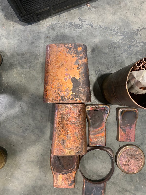 Untitled Untitled by Adam Cro, on Flickr This is not to the Wilson design but Pauls design of a GWR No4 boiler to give a much better scale look to the boiler. Adam |
|
|
|
Post by Cro on Apr 12, 2021 20:57:51 GMT
Boiler bits arrived, couldn’t help sitting them on the chassis to see how it will look.  Untitled Untitled by Adam Cro, on Flickr Post updated, haven't worked out how to do these photo links when using my phone. Adam |
|
twombo
Seasoned Member

Posts: 120 
|
Post by twombo on Apr 12, 2021 21:40:05 GMT
Adam.
Oh My! Plates, Sheets, and a lovely tapered barrel! That “checks all the boxes!” just what the Doctor ordered! That “throat” plate really catches my eye! It always amazes me the complex plate that can be made from a flat piece of copper! Gorgeous!
Mick
|
|
|
|
Post by Cro on Apr 13, 2021 7:29:33 GMT
Glad you like it Mick, really feels like a loco now it has the boiler sat there. Paul has done a lovely job on all of it and now its a case of making some working drawings before getting stuck in (at some point).
Adam
|
|
|
|
Post by Cro on Oct 8, 2021 11:10:53 GMT
Nothing much has happened since the last serious work on the tender back in January now but this week after clearing the bench from all the material stock I was sorting I have space for the City tender to have a home until the tank is finished so I decided I would start with a fair simple job - lifting links. I had these cast back in March and all they require is the links to be made, soldered and fitted. There are 2 on the rear of the tender and 2 in the coal space which may be a slightly different shape but this is the only photo I have so these will do.  Picture 151 Picture 151 by Adam Cro, on Flickr  thumbnail_DSCN5841 thumbnail_DSCN5841 by Adam Cro, on Flickr First up was to coil some brass rod to make 4 rings from, 3/32" dia rod was perfect size and a 3/8" dia. rod for wrapping round gave about the right size for the ring internal Dia. Held in the chuck with the tail of the brass rod nipped in a jaw it was rotated by hand and we were left with a brass spring.  Untitled Untitled by Adam Cro, on Flickr With a thin blade these were cut off into 4 individual rings.  Untitled Untitled by Adam Cro, on Flickr These are then fitted to each casting before closing up the gap and making them straight.  Untitled Untitled by Adam Cro, on Flickr Last job was to add a little flux to the joint and silver solder them together, quick clean up in the acid bath and they were ready to fit. I decided to use the M1.2 rivet head bolts I had for the tender kit so I can paint these and fit them separately as I think trying to paint them in situ will be a pain. I still have to fit them into the coal space which may be a pain to do as I can easily get a drill in there now but I'll think of something.  Untitled Untitled by Adam Cro, on Flickr Next up is the corner in fill pieces, not a simple job. The kit came with a 'trumpet' made on the CNC at Polly but sadly the profile doesn't really match that of the plates they have supplied. After some tedious fitting I got something that was close enough I could fit it and tidy up later so this will the job this afternoon before the beading starts - a job I hate but I have a plan that I hope will make the job easier.  Untitled Untitled by Adam Cro, on Flickr Once this is done it will be onto the beading on the coal rails, fitting them in place and the final soldering of the top coal plate and coal rails. Last details will be some boxes in the coal space around the water valve spindles and fitting the water gauge which will then see the tank done for now. I'm in two minds about a hand pump, I never use them on any of my locos but I know Dad likes to have them so I probably should fit something. More updates soon and progress on some fittings to come also. Adam |
|
|
|
Post by Cro on Oct 11, 2021 8:08:10 GMT
An unexpected weekend in the workshop as we were meant to have friends here this weekend but Jess has been ill with something that's going around at the moment, bit of a cold but not COVID, so we had to cancel. In between looking after her, the dogs, house duties I managed some time in the workshop to start the beading which I have put off for ages for fear of making a dogs dinner of it but I'm quite pleased with the progress so far. After the last post I said it was time to solder in the corners, Polly supplied a CNC trumpet but the profile wasn't great but leaving it over length and getting the best fit possible meant it was possible to clean it up and leaving it looking on. A bit more cleaning up to do but coming along ok.  Untitled Untitled by Adam Cro, on Flickr  Untitled Untitled by Adam Cro, on Flickr Now it was time for the beading and first of all I wanted to make sure I could attach it without the need for 100 clamps as the little experience I have had doing it before meant lots of clamping otherwise it just didn't go well. I also wanted to try and get the main beading strip right around the tender in once piece and not try and tidy up any joins. The beading supplied was 0.084" wide so I thought 1/32" rivets would do the job and I came up with the following drilling jig to allow me to get the holes central every time. I also thought 'oh the prototype has it rivetted this would be a lovely touch' but then saw the rivet spacing and decided that was far too much work and went for a more moderate 2" spacing to save my sanity.  Untitled Untitled by Adam Cro, on Flickr  Untitled Untitled by Adam Cro, on Flickr 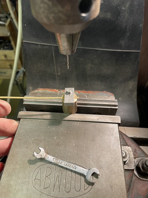 Untitled Untitled by Adam Cro, on Flickr This made the job dead easy in my eyes, once drilled it was a case of clamp it in place either side of the hole and spot through with the battery drill (carefully with 0.8mm drill), pop in the rivet and move on to the next one. I picked up some surgical forceps off eBay a few weeks back which are perfect for quickly clamping it in place to stop it all moving and also for soldering, a few quid each I think I'll get some more - LINK FOR THOSE INTERESTED I asked Jess what the best type would be for what I want (she's a vet and uses these things every day) and she said the mosquito straight 12cm would be best. 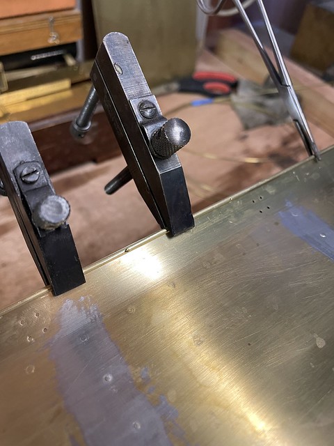 Untitled Untitled by Adam Cro, on Flickr I thought I would be clever and drill a hole for the corner before wrapping it round as I can't get bent beading in the drill jig, this was a stupid idea as obviously it just folded right at that point and wanted to break whilst I did the rest - don't know how I didn't see that coming but now I know for next time. 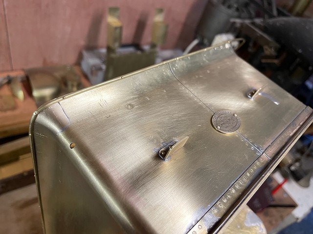 Untitled Untitled by Adam Cro, on Flickr And here we are all the way around and in one piece (just!). This is currently just placed there and held with the rivets in place as there is tidying up work on the sides I want to do before I do more soldering but before that there is still more beading to be done on the coal rails.  Untitled Untitled by Adam Cro, on Flickr This called for another bit of tooling in the way of a former to get the top edge curve. A bit of brass was used to create a 'button' with a curved groove in to sit over the top of the beading to keep it flat whilst pulling it around the radius.  Untitled Untitled by Adam Cro, on Flickr  Untitled Untitled by Adam Cro, on Flickr Once one end was done I drilled the holes along the top edge to get the position fixed before attempting the other end ensuring I didn't leave the bend too long, or too short. Then it was a case of clamps in various places and pulling it round the large radius. These have been left long for now as the coal rails will get soldered first and then the ends dressed to fit and blend into the initial beading, that's the plan anyway. It's now a case of doing the finishing off jobs such as fitting some more detail whilst accessible and then finalising the soldering order to make sure I don't disturb other areas as I go. If time is on my side this week I should see a lot of this done and it can then come back up to the office and not be a distraction from work. More to come soon. Adam |
|
|
|
Post by 92220 on Oct 11, 2021 8:28:14 GMT
Very nice job Adam! The beading looks great. I like the idea of riveting it on before soldering, and your way of centering the holes. The tip about the forceps was also very handy. Must get some for the small amount of beading there is on my loco.
Bob.
|
|
|
|
Post by Cro on Oct 25, 2021 15:51:56 GMT
Further progress on the tender tank see's all of the soldering now complete. It took longer than expecting to complete each step as a lot of cleaning up needed between each step and didn't want to rush anything and make a mistake. First up was soldering the beading, this was an easy job with the beading rivetted on and the forceps everything stayed where it was supposed to. The coal rail brackets were also soldered at the same time so I could clean up the external rivets before fitted to the tank.  Untitled Untitled by Adam Cro, on Flickr  Untitled Untitled by Adam Cro, on Flickr Next up was to fit the lifting links in the coal space.  Untitled Untitled by Adam Cro, on Flickr The came the time to fit the top plate. I had already made the bases for the air vents and I will look to make the rest of these soon and they can screw straight on. The worst thing with fitting the top plate was the slight misalignment of the two sides during the first soldering, rivets went in down one side perfect, the other side.....not so much. The worst thing with all of it is there is no way to get in there to fasten the top down to the baffles, angles or coal space so when things got hot things did try and move around.  Untitled Untitled by Adam Cro, on Flickr Not as neat as I would like but it will clean up. 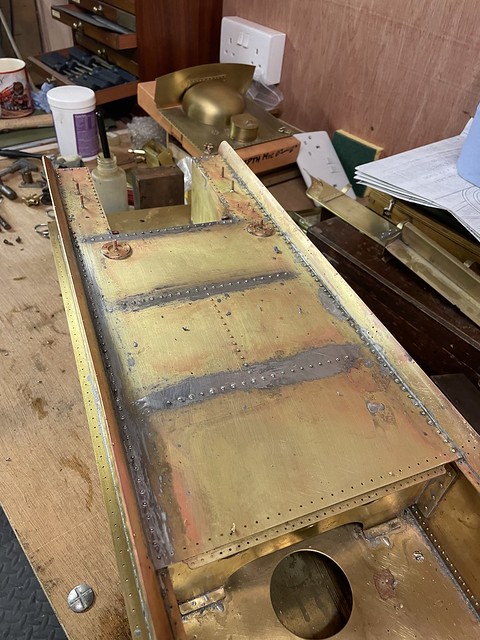 Untitled Untitled by Adam Cro, on Flickr The worst thing was this did cause some leaks around the coal space from earlier soldering which I had to chase around but its all sealed now. Last job was to fit the side coal rails, rear and dummy dome section. I have now started the big clean up for any solder runs and the big task of getting all the rivets flush on the outside of the tank and the angle with the hope of no witness marks when done.  Untitled Untitled by Adam Cro, on Flickr  Untitled Untitled by Adam Cro, on Flickr  Untitled Untitled by Adam Cro, on Flickr  Untitled Untitled by Adam Cro, on Flickr The list of remaining jobs is now: Lamp brackets Air Vents False floor and boxes that fit around water valves (no idea what they were for but they are different on both ides and something else to add as can be seen here.  thumbnail_DSCN5841 thumbnail_DSCN5841 by Adam Cro, on Flickr Hand rails and the final clean up, think I might stick a coat of primer on once done but undecided. I still have the brake gear and associated parts to do at a later date. This is all good practice for the BR1F tender I'll be starting soon for the 9f now my tender has sold - at least this tender I can show the old man what I've been doing! Thanks all, Adam |
|