dalboy
E-xcellent poster

Posts: 235
|
Post by dalboy on Aug 9, 2022 19:26:03 GMT
Spent the other day boring the cylinders quite pleased with the finish. I also managed today to take the mounting flanges down to 1/8" and do a test fit to the frames a very light filing was needed to get them to fit comfortably with no slop I must get back to the coupling rods before I go to far
 DSCF2713 DSCF2713 by Dalboy, on Flickr  DSCF2715 DSCF2715 by Dalboy, on Flickr 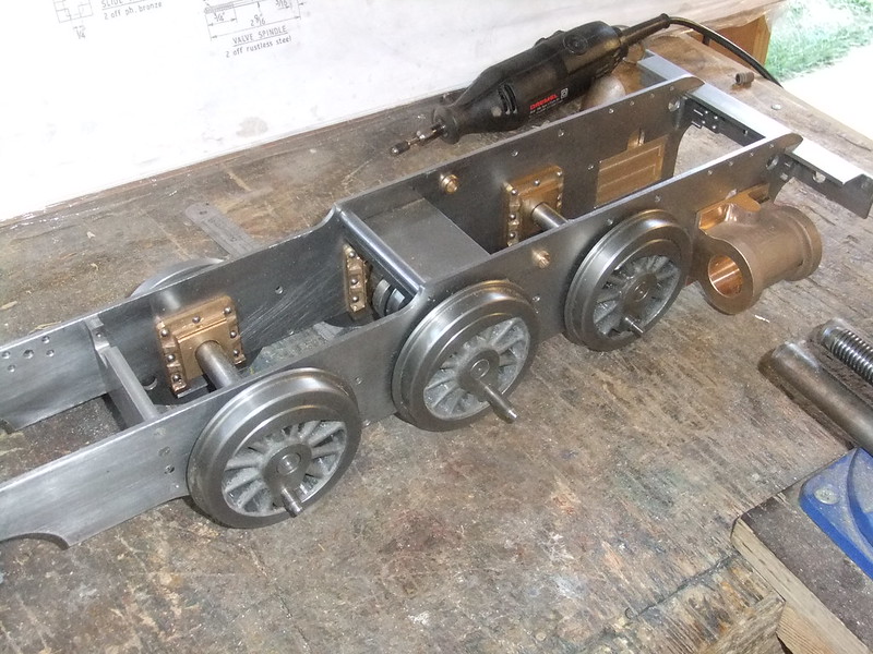 DSCF2721 DSCF2721 by Dalboy, on Flickr |
|
dalboy
E-xcellent poster
Posts: 235
|
Post by dalboy on Aug 10, 2022 21:04:58 GMT
Too hot to spend a lot of time in the workshop but did manage to cut out two steam chest covers from some brass which arrived yesterday. The milling cutter also arrived today to do the posts in the cylinder casting. No Pictures as the covers are just two rectangles of brass not worth looking at
|
|
|
|
Post by runner42 on Aug 11, 2022 0:18:04 GMT
Looking at the photo for the cylinders, it appears that the distance of the valve face from the bolting face is undersize. The second photo of the cylinders put in place suggests that the valve face is just flush with the inside of the mainframe, this will worsen the known problem of the valve operating levers fouling on the front hornblocks. The fix is to put a dog leg in the valve operating levers. Brian PS A photo to show how far the valve face extends beyond the inner face of the mainframe to overcome the interference of the valve operating rods with the front hornblocks.  valve face beyond inside frames valve face beyond inside frames by Brian Leach, on Flickr |
|
dalboy
E-xcellent poster
Posts: 235
|
Post by dalboy on Aug 11, 2022 7:41:29 GMT
Looking at the photo for the cylinders, it appears that the distance of the valve face from the bolting face is undersize. The second photo of the cylinders put in place suggests that the valve face is just flush with the inside of the mainframe, this will worsen the known problem of the valve operating levers fouling on the front hornblocks. The fix is to put a dog leg in the valve operating levers. Brian PS A photo to show how far the valve face extends beyond the inner face of the mainframe to overcome the interference of the valve operating rods with the front hornblocks Thank you Brian have sat and double checked the drawing and can now see where I went wrong. I knew that I would make mistakes but why did I have to do it to and expensive part of the build  . I am going to bite the bullet and I will order some new ones rather than try to bodge my way out and looking at your photo there is not much room for an offset.
At least I can be getting on with other things on the build. All this for a mistake of 1/16" but essential. Looking at your photo it however does look like a little more than that.
Thank you anyway rather find this out now than later in the build and all down to a small case of missing a vital measurement by me. I normally am a person that double checks everything.
I noticed in your photo that the studs holding the steam chest appear not to line up on the bottom row is this a trick of the photo or is there a reason as the plans show them directly opposite of each other
Derek
|
|
|
|
Post by doubletop on Aug 11, 2022 7:54:14 GMT
Before you go much further I'd suggest you investigate the alternative methods others have used for the inlet and exhaust for the cyliders and steam chests. Although workable the method Martin Evans used is a real PITA when it comes to maintenance. I can't point you at any particular approach just that I know they are out there. Mine was done the Evans way hence my comment. There is also a modification to add a brace between the frames rather than expecting the steam pipe and steam chests to do it for you.  Whether it is required or not is open to discussion but there is an argument that it helps. I had a problem at my track with gauging which required the float on the axles to be maximised. I did the mod to ensure the axleboxes didnt splay. Pete |
|
|
|
Post by doubletop on Aug 11, 2022 8:17:03 GMT
Looking at the photo for the cylinders, it appears that the distance of the valve face from the bolting face is undersize. The second photo of the cylinders put in place suggests that the valve face is just flush with the inside of the mainframe, this will worsen the known problem of the valve operating levers fouling on the front hornblocks. The fix is to put a dog leg in the valve operating levers. Brian PS A photo to show how far the valve face extends beyond the inner face of the mainframe to overcome the interference of the valve operating rods with the front hornblocks Thank you Brian have sat and double checked the drawing and can now see where I went wrong. I knew that I would make mistakes but why did I have to do it to and expensive part of the build . I am going to bite the bullet and I will order some new ones rather than try to bodge my way out and looking at your photo there is not much room for an offset. At least I can be getting on with other things on the build. All this for a mistake of 1/16" but essential. Looking at your photo it however does look like a little more than that. Thank you anyway rather find this out now than later in the build and all down to a small case of missing a vital measurement by me. I normally am a person that double checks everything. I noticed in your photo that the studs holding the steam chest appear not to line up on the bottom row is this a trick of the photo or is there a reason as the plans show them directly opposite of each other
Derek
Now reading Brians comment and looking at the photo of my Rob Roy it appears that my valve face is flush with the frames. I can only imagine it was dealt with by the thickness of the steam chests and valve block compensating to re-align the valve rods. Which would be cheaper than making new cylinders. The alternative would be a thin packer plate creating a new valve face. All that said my operating levers are very close to the axle boxes. But it would appear that the approach my Dad took was make special bolts. Check the heads of the bolts, they are virtually flat  Pete |
|
stevep
Elder Statesman

Posts: 1,070
|
Post by stevep on Aug 11, 2022 8:25:14 GMT
Having read the book (several times) before making my Rob Roy, I noticed the offset valve rod connectors in the photos, and tried to do something about it. So I made my valve faces (IIRC) 1/6" further out than drawn, and also put the valve rod (again IIRC) 1/16" higher in to steam chest. This took up the 1/8" difference and my connectors are straight (like Pete's). I also have bolts like Pete's with very thin heads, to clear the axleboxes.
The downside of this is that the space between the steam chests, where the steam pipes screw in, is reduced and makes the whole assembly a bit awkward. Rex (of this parish, and from Andover club) took the step of not using steam pipes screwed into the covers, but made banjo fittings on the top (bottom?) of his steam chests. I think he posted a picture of it on here once. Maybe he can re-post it in your thread for future generations?
|
|
|
|
Post by doubletop on Aug 11, 2022 8:29:02 GMT
Having read the book (several times) before making my Rob Roy, I noticed the offset valve rod connectors in the photos, and tried to do something about it. So I made my valve faces (IIRC) 1/6" further out than drawn, and also put the valve rod (again IIRC) 1/16" higher in to steam chest. This took up the 1/8" difference and my connectors are straight (like Pete's). I also have bolts like Pete's with very thin heads, to clear the axleboxes. The downside of this is that the space between the steam chests, where the steam pipes screw in, is reduced and makes the whole assembly a bit awkward. Rex (of this parish, and from Andover club) took the step of not using steam pipes screwed into the covers, but made banjo fittings on the top (bottom?) of his steam chests. I think he posted a picture of it on here once. Maybe he can re-post it in your thread for future generations? I was probably Rex's approach that I was referring to. If a add him to the comment he may pick up ( Rex Hanman ) Talking about Rex and digging around for my Rob Roy photos just found this from the 2018 Rob Roy Rally. Happy days.  Pete |
|
|
|
Post by Rex Hanman on Aug 11, 2022 21:20:25 GMT
Yep, posted this back in May...... Several builders have followed suit. Phil, I think I gave wrong info on the piping recommendation. The piping I am referring to is the very short section between the valve chests. I am working from memory, and I am not sure if it was exhaust or intake. Sorry for the confusion. Rick Like this.... 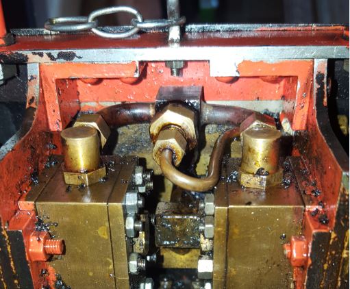 It's so much easier than struggling to get the short piece of pipe between the steam chest covers. The pipe with the u-bend is the oil feed from the lubricator. Hope this helps, Rex Rather than making new cylinders or valve chests, you could silver solder a 1/8th" brass spacer onto the mating face of the valve chest then make new valve nuts 1/8th" thicker. Got to be cheaper than new cylinders! |
|
|
|
Post by runner42 on Aug 12, 2022 0:15:49 GMT
Yes Rex has provided the answer, which is what I did on the lower cylinder and fit an 1/8" spacer because I became aware of the problem too late. If you include the inlet and exhaust ports in the spacer you don't have to alter the valves at all. Since the modification puts the valve chests even closer making the valve chest covers as the steam input even more difficult I also used the fromt end of the steam chest as the steam inlet as Rex has done. The steam chest studs are slightly offset the end ones are not on the same line as the side ones. Check the steam chest cover drawing will make this obvious. Go with the existing cylinders and make the spacers, if you are bold enough you could permanently fix the spacer to the cylinder by soldering. I did not and just had to have another face to face seal included.
Brian
|
|
dalboy
E-xcellent poster
Posts: 235
|
Post by dalboy on Aug 12, 2022 12:00:24 GMT
Thank you guys for all the advice. I did think about silver soldering a packer piece on my thoughts on that are would the silver solder penetrate deep enough so that where the ports are would it be enough to seal those. I suppose that i could experiment as i have some old unknown silver solder that I could try on some scrape metal first then buy the correct grade for the main job. I will be phoning Cupalloy as I have some other questions to ask them. I do own a bullfinch brazing torch with various nozzles already but may need some other source of heat later on
|
|
millman
Part of the e-furniture

Posts: 297 
|
Post by millman on Aug 12, 2022 12:07:06 GMT
Dalboy if you were to tin the packer piece first you would be almost guaranteed to get a seal around the ports, or you could use silver solder paint or foil. Maybe speak to someone like Cup alloys, they are very friendly and helpful.
|
|
dalboy
E-xcellent poster
Posts: 235
|
Post by dalboy on Aug 12, 2022 19:48:50 GMT
Spoke to Cup Alloy and have ordered some silver solder to add on top the cylinder casting which will hopefully solve the problem. As stated by Rex cheaper than two castings which if the were not on annual closedown I would have ordered yesterday. As the solder will not be here until Wednesday/Thursday the weather will be cooler to do this job then.
|
|
|
|
Post by Rex Hanman on Aug 12, 2022 20:50:00 GMT
To be honest I would solder the spacer/packing piece to the face of the valve chest rather than onto the cylinder, much less metal to heat up than the cylinder. Thus.... 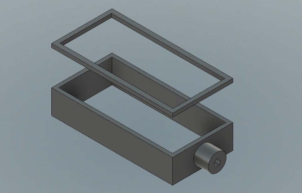 |
|
dalboy
E-xcellent poster
Posts: 235
|
Post by dalboy on Aug 12, 2022 21:05:44 GMT
To be honest I would solder the spacer/packing piece to the face of the valve chest rather than onto the cylinder, much less metal to heat up than the cylinder. Thus.... Would that not then effect the slide valve. |
|
|
|
Post by Rex Hanman on Aug 12, 2022 22:24:52 GMT
Yes, but just make new ones 1/8th" taller or silver solder a 1/8th thick spacer on the face of the existing valve. Or even make the nut that sits in the valve 1/8th bigger to compensate. Got to be cheaper/easier than messing with the already machined port face of the cylinder. Or you can resort to the usual method of making offset valve crossheads. There's more than one way around the problem. Judging by the quality of your work so far, I'm sure whichever method you choose will be successful.  |
|
|
|
Post by philh1aa on Aug 13, 2022 12:49:27 GMT
I don't know whether I am too late but I have the same offset problem on my Rob Roy. Even careful machining of the cylinders would not produce a straight valve rod connection. I have made two very simple off-set valve cross heads as Rex has suggested. I am not keen on the idea of heating up some nicely machined cylinders or steam chests if you can help it.
Phil H
|
|
dalboy
E-xcellent poster
Posts: 235
|
Post by dalboy on Aug 14, 2022 12:29:22 GMT
Will give this some thought at which approach I will take. Thank you all for the suggestions which give me something to think about
|
|
|
|
Post by doubletop on Aug 14, 2022 20:37:08 GMT
I don't know whether I am too late but I have the same offset problem on my Rob Roy. Even careful machining of the cylinders would not produce a straight valve rod connection. I have made two very simple off-set valve cross heads as Rex has suggested. I am not keen on the idea of heating up some nicely machined cylinders or steam chests if you can help it. Phil H Really there is no need to heat up anything. Any spacer parts can be clamped together with the studs that hold the cylinder and steamchest together. Just make allowance for the thickness of any gaskets. Paper or silicon. Pete |
|
|
|
Post by philh1aa on Aug 15, 2022 14:46:56 GMT
Really there is no need to heat up anything. Any spacer parts can be clamped together with the studs that hold the cylinder and steamchest together. Just make allowance for the thickness of any gaskets. Paper or silicon. PetePete,I had a similar thought - Infact I had machined a similar spacer myself but it looks like the slide valves etc have already been machined and he would need to start monkeying around with those parts too. I side lined my spacers and opted for what appears to be some very simple off set crossheads. Phil H |
|


 . I am going to bite the bullet and I will order some new ones rather than try to bodge my way out and looking at your photo there is not much room for an offset.


