44767
Statesman
 
Posts: 538
|
Post by 44767 on Jul 3, 2018 11:41:11 GMT
Thanks for your notes about the casting of your wheels, Bob. I think the foundry is going to cast these with the wheels horizontal which gets around the problems you were talking of. In fact, I think they are going to stack them feeder to boss, effectively having the tree go right through the middle of the casting. This works OK in cast iron but is not so good with steel.
I have ordered enough for five locos this time which will give enough castings for me, the trust and the others building their own to get on with.
|
|
44767
Statesman
 
Posts: 538
|
Post by 44767 on Mar 7, 2019 10:03:43 GMT
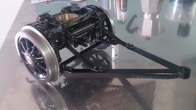
In the time I've been away from here I've done quite a bit to the models. I just haven't had the time to add it to the forum. This is meant to be a record of the build so here is a bit to go on with. I have assembled the first pony truck so that I can work out the best way to paint and assemble it. Indeed some has not been painted as I have been experimenting with chemical colouring of the steel at home. More of that later. As I come to parts I have not made or finished I have been doing enough for all the trucks. Here's the first one:  Actually some of you will recognise it as a 9F pony truck. It has 90% the same parts as the other standard pony trucks and only differs in the way the axlebox guides are made and the bridle frame which is a bit longer. I know Bob has already finished his but he didn't have to paint his to look good! |
|
|
|
Post by Jim on Mar 7, 2019 17:46:07 GMT
Superb work as always Mike, simply superb and great to see a post from you too.
Jim
|
|
44767
Statesman
 
Posts: 538
|
Post by 44767 on Mar 11, 2019 10:50:03 GMT
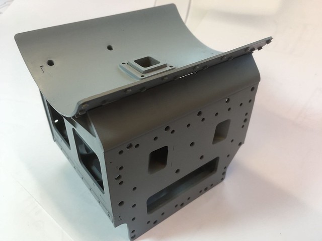
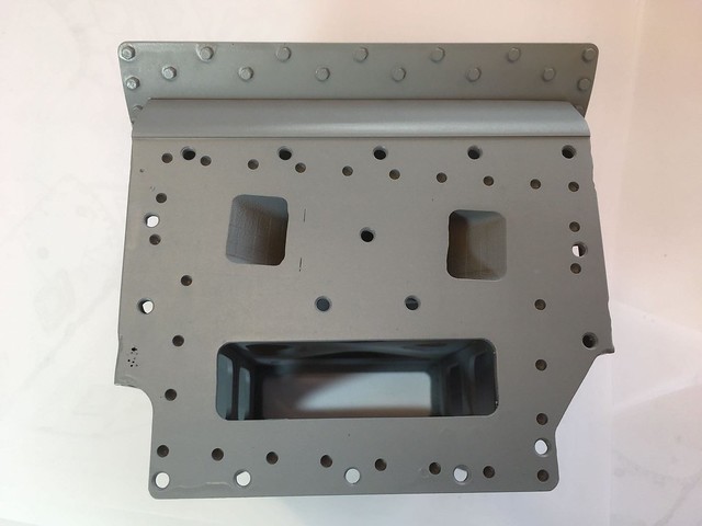
Two or three days ago one of the chaps building this model from my drawings, castings etc. sent these photos of his smokebox saddle all fabricated and machined. He was very pleased, having put all the holes in to the dimensions on the drawing, that it lined up perfectly for location and hole positions. That's the sort of feedback I like!   The large holes are M4. They are for permanent countersunk screws holding the smokebox into the frame structure. The ones you see around the outside are recesses which correspond to the stud positions in the frame which hold the cylinders on. These recesses allow the stud to go right through the frame plate thus giving it full engagement and it also provides a stop so all the studs protrude the same amount. Also, there are two dowel holes inline with the cylinder centreline which locate the cylinders and take its thrust, although I'm sure all those studs and properly tightened nuts will do that job quite well! |
|
JonL
Elder Statesman
   WWSME (Wiltshire)
Posts: 2,990
|
Post by JonL on Mar 13, 2019 10:57:41 GMT
Only just started looking at this thread, inspirational work.
|
|
44767
Statesman
 
Posts: 538
|
Post by 44767 on Apr 20, 2019 2:02:44 GMT
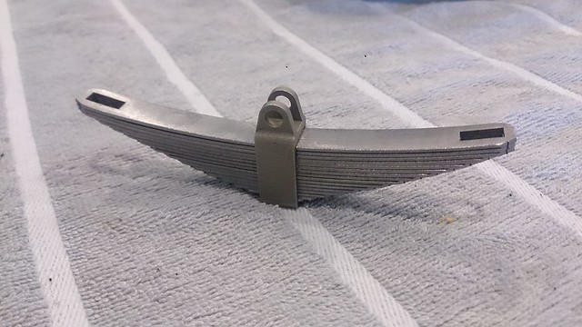
I have been working on the main axlebox suspension. Here's the CAD model of the assembly.  The spring hangers were done a while ago and the first few axleboxes have been cast in cast iron from printed waxes. The remaining will be from moulded waxes to save on cost. The gimble is from a moulded wax having made a master pattern for it. The spring buckles are from printed waxes and, I think, the future ones will be too as they are very much more accurate geometrically so they should not need machining, They are done in a material called white bronze which I found at a different foundry. It is as strong as steel, as is silicon bronze, but it is very much harder than silicon bronze. I wanted the leaves in the springs to be scale thickness so that I could have the correct number of them but springs don't scale in performance and so would be far too stiff in spring steel. I saw an idea for overcoming this by chance so I don't claim the idea to be mine but before that I had not seen it. Effectively the middle of the spring leaves are taken out leaving only a thin strip down each side. I put in some cross ties to help stop the springs from splaying out or twisting and came up with this- one complete set of springs for one assembly.  This I had laser cut from pre-hardened and tempered 18 gauge (1.2mm) spring steel strip. I made a tool for forming the set which wraps the leaf around a diameter. All leaves are done and for some reason, they all nest perfectly. Here's the finished result. I'm very happy with it and I think I came up with just the right stiffness.    That should keep the builders happy! Mike |
|
|
|
Post by 92220 on Apr 20, 2019 7:33:28 GMT
Brilliant job Mike! Taking the middle out of the spring leafs works well to get a scale deflection.
Bob.
|
|
|
|
Post by Roger on Apr 21, 2019 7:05:36 GMT
Very neat, that's a really good solution. It seems unlikely that you'll get the right stiffness first time, but it's easy enough to make a range of intermediate leaves that you can swap around to get it exactly how it's needed.
This is where modern methods really come into their own.
|
|
|
|
Post by ettingtonliam on Apr 21, 2019 8:56:09 GMT
Tying this thread into Roger's thread, do the feedwater pipes pass up though the tanks in a tube, and if so, does the position of the tube align with the clack, or is it offset?
|
|
44767
Statesman
 
Posts: 538
|
Post by 44767 on Apr 21, 2019 10:49:19 GMT
I know the feed water pipe goes through a pipe which itself goes through the tank, and if I had to guess, I'd have said it was in line with the clacks but it is not. See the GA here:  It's not that having a joggle is particularly bad, it's having it go through the tank that is a real pain on the model as it means having to disconnect the pipe to get the tank off. I am going to have the "pipe" as a u-section in the tank with the top of the tank disguising this so the tank may be removed without touching the pipework. |
|
|
|
Post by ettingtonliam on Apr 22, 2019 6:51:20 GMT
Thanks for that. I think we can conclude now that the offset is deliberate, and all I can think is that it is so to enable the fitter, once he's disconnected the pipe top and bottom, to rotate it to swing the top flange well clear of the clack before pulling it out of the tank.
|
|
44767
Statesman
 
Posts: 538
|
Post by 44767 on Apr 25, 2019 8:38:04 GMT
Thanks for that. I think we can conclude now that the offset is deliberate, and all I can think is that it is so to enable the fitter, once he's disconnected the pipe top and bottom, to rotate it to swing the top flange well clear of the clack before pulling it out of the tank. I think it's more to do with routing the pipe underneath the tanks. If it were to go to a point where it would be in line with the clacks, it would have trouble getting passed the motion and expansion link brackets. |
|
44767
Statesman
 
Posts: 538
|
Post by 44767 on Apr 30, 2019 11:14:30 GMT
I have some photos of one of the models getting built. This is virtually the whole frame assembly but without the brackets on the outside of the frames at this stage:    As you can imagine, I am very happy this is coming together so well. Cheers,Mike |
|
JonL
Elder Statesman
   WWSME (Wiltshire)
Posts: 2,990
|
Post by JonL on May 5, 2019 20:42:22 GMT
Astonishing. Good work.
|
|
44767
Statesman
 
Posts: 538
|
Post by 44767 on May 9, 2019 17:35:33 GMT
Not many know I am here in the UK now and will be at the Doncaster exhibition on Friday and Sunday. If anyone would like to chat we can arrange a time and place to meet.
|
|
|
|
Post by Roger on May 9, 2019 19:13:05 GMT
Not many know I am here in the UK now and will be at the Doncaster exhibition on Friday and Sunday. If anyone would like to chat we can arrange a time and place to meet. A group of us are aiming to meet from say twelve onwards upstairs where we will be gathering around a table. I'll look out for you. |
|
44767
Statesman
 
Posts: 538
|
Post by 44767 on May 10, 2019 2:19:23 GMT
OK Roger. I know what you look like! See you tomorrow.
|
|
44767
Statesman
 
Posts: 538
|
Post by 44767 on Aug 5, 2019 11:22:11 GMT
Here's a little update on progress. I picked up the motion brackets last week. These are cast in white bronze- a tri-metal alloy of 55% copper, 30% tin and 15% zinc. It is very hard compared to silicon bronze, as strong as steel, does not tarnish, has very good corrosion resistance, is non-magnetic, solders well, casts well, has a low coefficient of friction and has the colour of sterling silver. For some or all of these properties it is used for electrical connections, for jewelry, and.... model engineering! I measured the castings and found that all dimensions were within 0.1mm of the design size.  |
|
|
|
Post by ettingtonliam on Aug 5, 2019 13:10:50 GMT
Nice looking castings, but what is the machinability like if its so hard compared to silicon bronze?
|
|
44767
Statesman
 
Posts: 538
|
Post by 44767 on Aug 5, 2019 21:29:39 GMT
It machines very much like silicon bronze. As with most materials, you need sharp tooling but it does machine nicely. When I said hard, I meant in terms of its elasticity; it has a much higher Young's modulus and therefore is more springy unlike Silicon bronze which yeilds at much lower pressures. I have a 4mm diameter rod of it and one of silicon bronze which I show people. The silicon bronze rod is easily bent between thumbs and fingers but everyone struggles to bend the white bronze one.
|
|