|
|
Post by Doug on Sept 6, 2015 16:01:28 GMT
Ok so what has this done for me, well as far as I can see it has transformed it the surface finish is exceptional and the spindle chatter has almost stopped I will be giving it. A really good test soon with my eccentric rods.
|
|
|
|
Post by Roger on Sept 6, 2015 20:26:17 GMT
What a promising start. It's easy to underestimate how rigidity affects things. My excellent parting tool starting playing up, it became hopeless at parting off Stainless Steel and Silver Steel which it used to do easily. On closer inspection, there was a small area of swarf that had become compacted and stuck onto one of the surfaces of the quick change toolholder. It was really quite small, but it was clearly enough to stop the holder from seating rigidly against the tool post. With that cleaned up, it's back to normal. I was really surprised that something so small could make such a huge difference.
|
|
|
|
Post by Doug on Nov 11, 2015 10:23:28 GMT
Ok more modifications are afoot not only am i currently sorting my 4th axis pics and write up to follow. I have decided to alter my mill further by adding ball screws to the x and y axis the main reason for this is i have continusly had to keep altering and checking for backlash which is being generated in the delrin nuts. My x and y axis are both still M8 bar so have a pitch of 1.25mm the z axis has a ballscrew and has a pitch of 5mm. i did look at swapping the delrin for a more robust cast iron but the cost is equvelent to the ball screw £19 for the x axis 350mm and i already have a suitable y axis 200mm one. the one issue i do have is space so i may end up having to alter the x/y tables and put linear rails on them. i dont want to do this as it will be quite a big job but it may be essential to get the screws in so the choice may not be mine in the end. The one down side with adding linear rails is the height of the tables will increase reducing the working area. I will add more details as i get into this build. 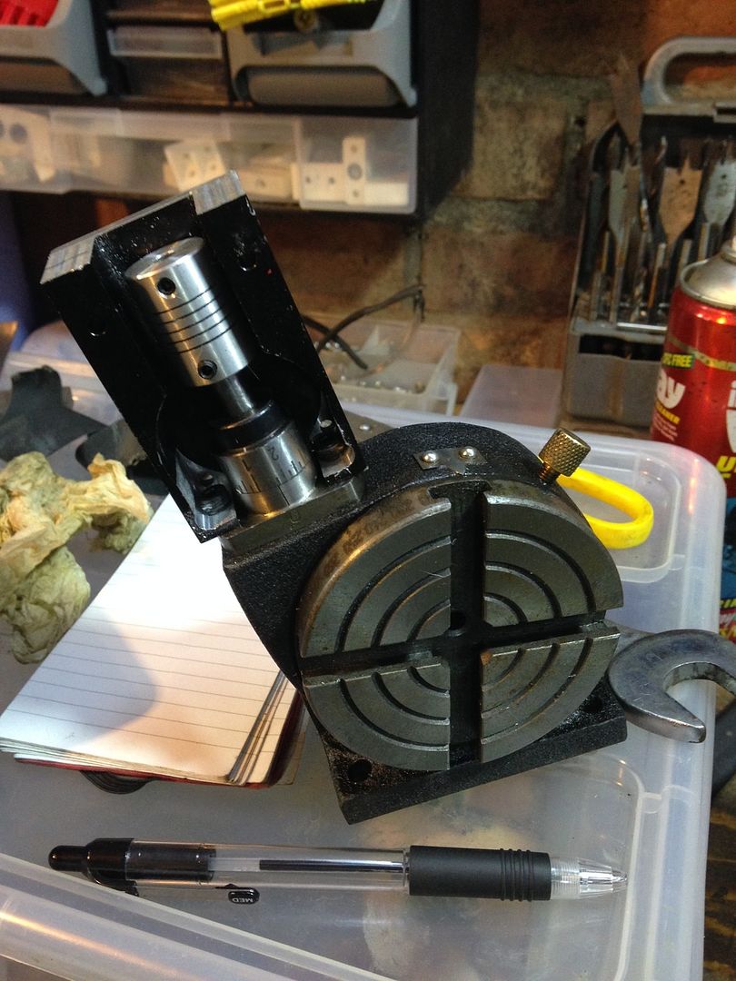 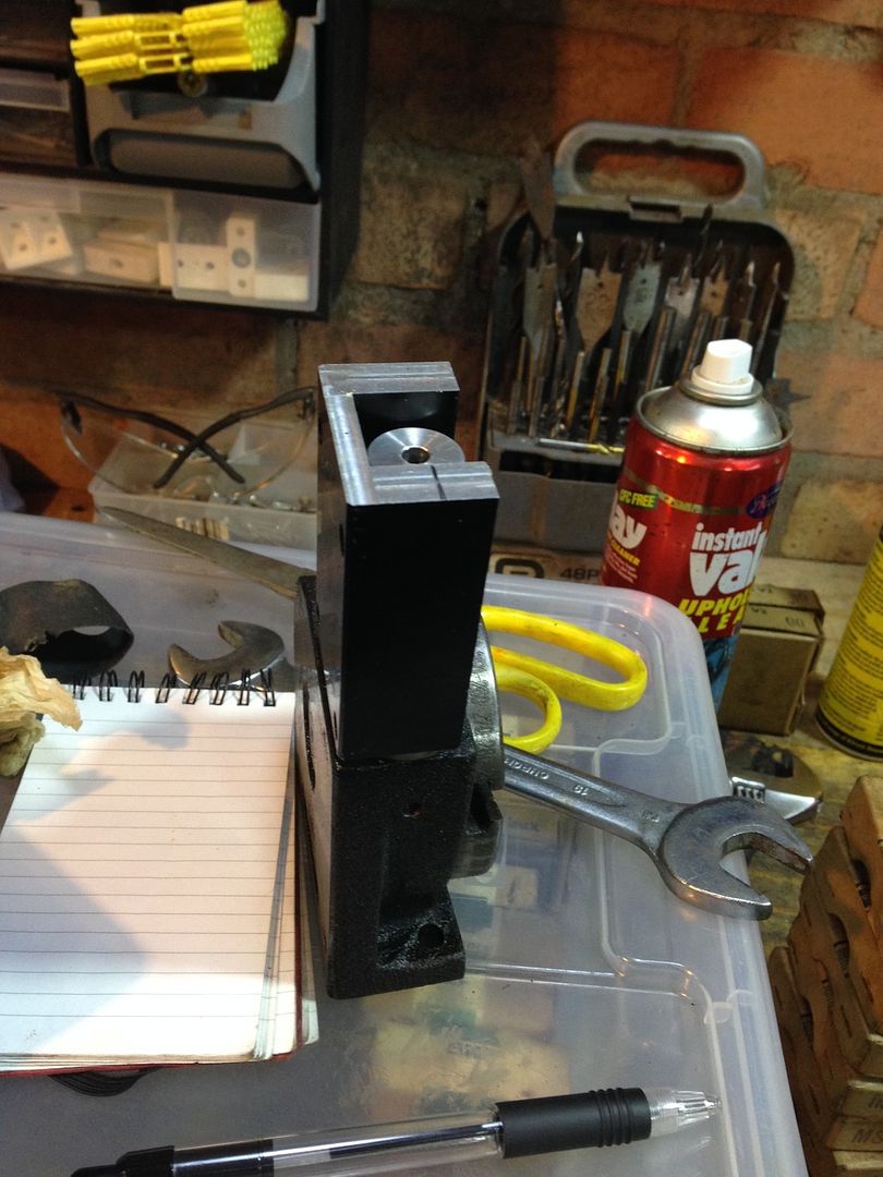 Just making the motor adapter plate |
|
|
|
Post by Roger on Nov 14, 2015 23:27:15 GMT
I'm not sure linear rails is a good idea, they won't be as rigid as the setup you currently have.
The size of ballscrews is a problem, I had to look really hard to find some with small enough nuts. Most of them have round flanges and those aren't much good under the table I've got. I suppose you could machine off the parts that get in the way. I had to take an angle grinder to mine on the X-axis to get it to fit.
|
|
|
|
Post by Doug on Nov 15, 2015 20:05:20 GMT
Ok I have got the rotary table all sorted made an adapter plate for the tiny motor on the CNC 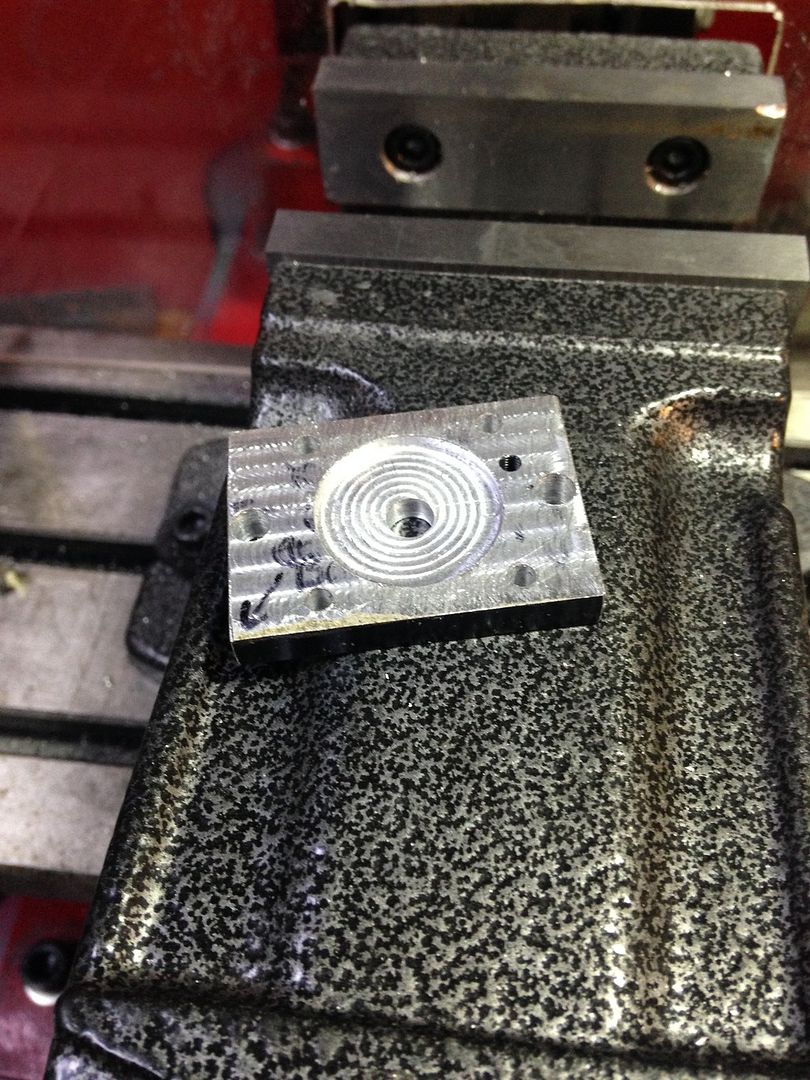 Connected up the motor it's still a revelation how good the fit is using CNC it just dropped together 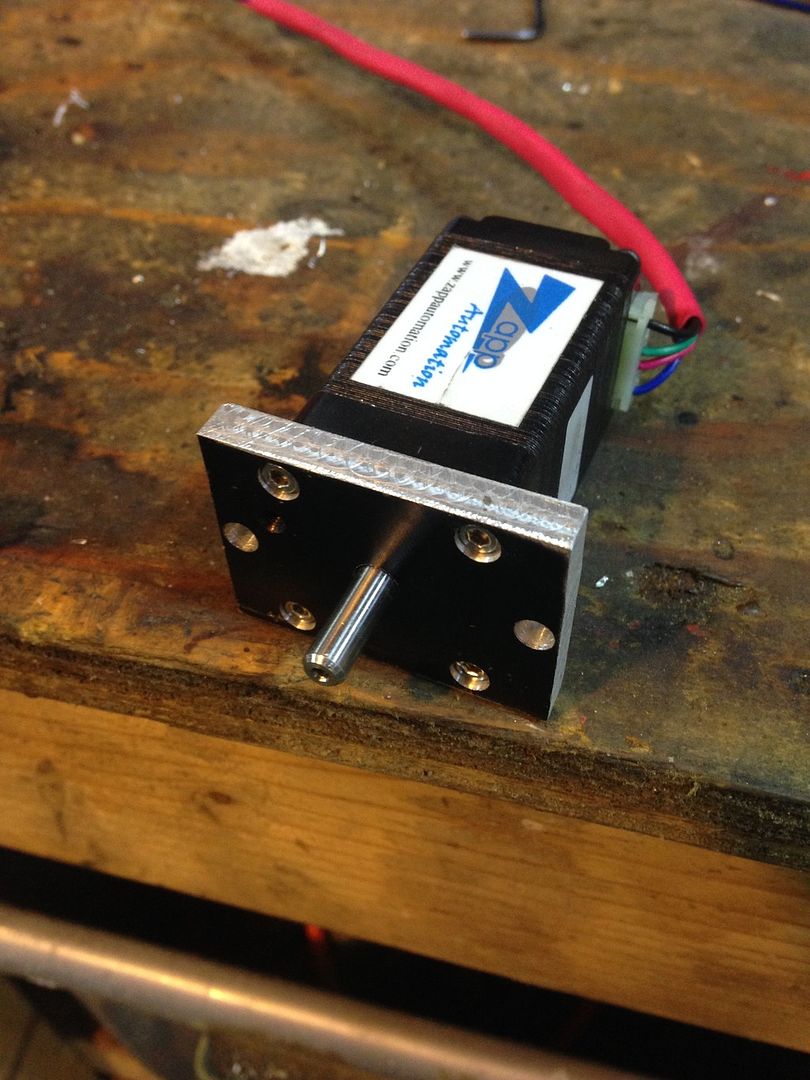 A couple of shots of the table coupling I've got to make a fitted plate to enclose the coupling but it's now functional 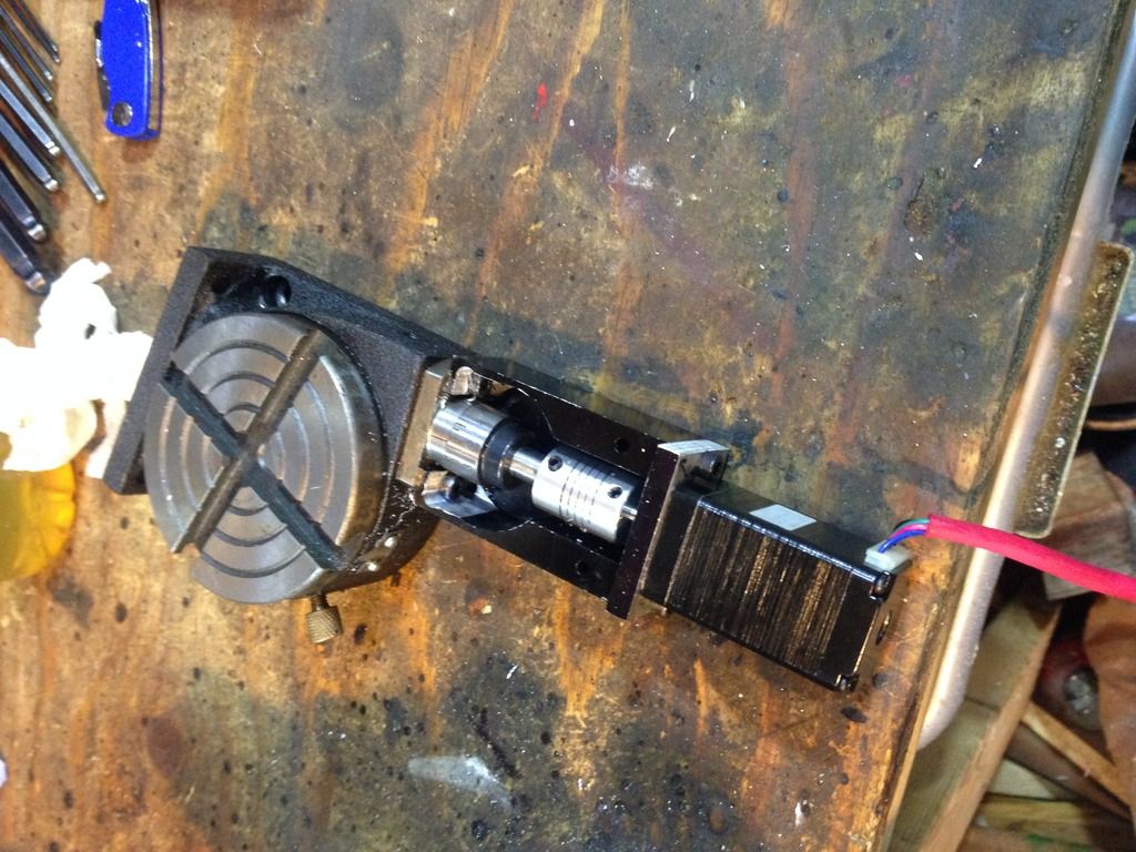 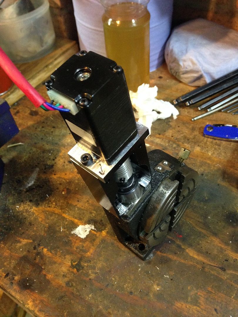 |
|
|
|
Post by Roger on Nov 15, 2015 20:12:28 GMT
That's very neat Doug. I'm curious to know how you intend to deal with the backlash issues?
|
|
|
|
Post by Doug on Nov 15, 2015 22:04:20 GMT
I already have sorted the backlash, I am sure I mentioned above somewhere, anyway the short version is you engage the worm into the wheel at the loosest spot then run the table via a pillar drill in my case forward for 12-24 hours then backwards via a pistol drill for same amount of time and then strip and degrease and then re lube. It's pretty good now with only the slightest tight spot and no measured backlash.
it will also get better with use.
|
|
|
|
Post by Roger on Nov 15, 2015 22:25:40 GMT
Excellent, I think I remember now you mention it. It's my age...
|
|
|
|
Post by ejparrott on Nov 16, 2015 9:50:25 GMT
.......engage the worm into the wheel at the loosest spot..... Tightest? |
|
|
|
Post by Doug on Nov 16, 2015 9:58:11 GMT
.......engage the worm into the wheel at the loosest spot..... Tightest? noo loosest (the lowest spot) if you engage into the tightest (highest spot) bit then the low or loosest bit would be very sloppy. i basically indused alot of wear in the crown gear till it was worn level. it is fairly standard stuff we do it alot at work with our cheap rotory tables because they have backlash and we use direct encoders and they wont tollerate it. |
|
|
|
Post by ejparrott on Nov 16, 2015 10:01:02 GMT
But if you engage it at the loosest position is there not already a lot of backlash? Just thinking of the worm boxes I build up where I set the backlash between the too.
|
|
|
|
Post by Roger on Nov 16, 2015 10:28:34 GMT
I think this is a misunderstanding of the wording, you both mean the same thing. I was going to use a toothed belt on my universal rotary table to convert it to a 4th axis, but it's really useful as it is. Knowing that this works, I might buy a small tilting rotary table instead and do what Doug has done. I'm surprised this works to be honest, but it's a neat way out of a tricky problem.
|
|
|
|
Post by Doug on Nov 16, 2015 14:23:46 GMT
But if you engage it at the loosest position is there not already a lot of backlash? Just thinking of the worm boxes I build up where I set the backlash between the too. hi Ed we are as roger says, talking about the same thing but in different languages the below diagram shows what i ment to say if the worm is adjusted to "fit" the tightest spot on the crown gear (shown oval in black) then it becomes loose (shows back lash) at the low spot on the gear this is the red circle and it would revolve very easily with no decernable tight spots, however if it is adjusted to fit at the losest spot shown as the gray worm position then it would get tight twice on every rotation untill it was worn in to the size of the orange circle at which point the crown gear and worm are bedded in to the point where there is very little backlash in the system if you were to change direction. 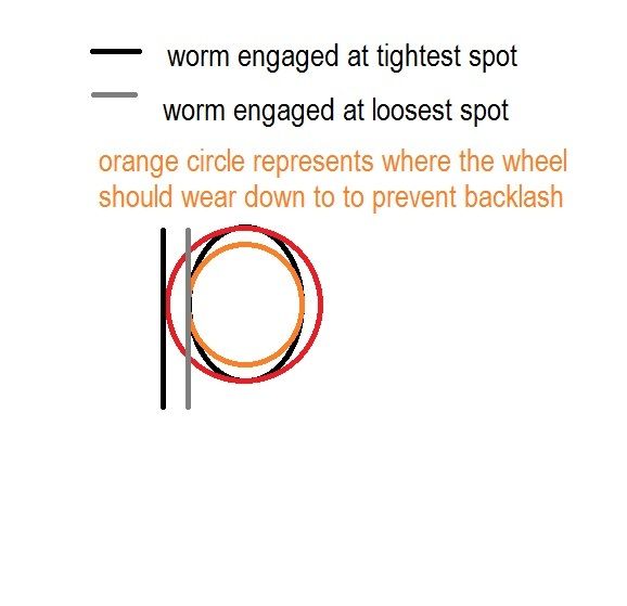 in reality there is nearly always a couple of tight spots but wearing it in helps to free this off to the point that the motor can push past the tight bits and give you a fairly acurate table. |
|
|
|
Post by Roger on Nov 16, 2015 14:42:23 GMT
Thanks for making that clear. I reckon this is a very useful ruse.
|
|
|
|
Post by ejparrott on Nov 16, 2015 17:59:54 GMT
Got you, yes we were talking about the same thing
|
|
|
|
Post by Doug on Nov 21, 2015 21:16:20 GMT
I had a hour on the y axis ballscrew today, happily it fits in the gap without having to mill any metal off. I have measured it all up to build a model in CAD but...... My computer has died, in all the years I have had PCs this is the first motherboard failure I have ever had. Luckily a new Optiplex 755 motherboard is only £12 so I am not crying and I have treated myself to another 4Gb of ram as well as my design for my Bulied is getting complex and I don't want to stall my cad program.
Once I get fixed I will model the two bits I need for the ball screw to fit right in and I will then be on to the x axis which happily has lots more room.
|
|
|
|
Post by Roger on Nov 21, 2015 21:21:28 GMT
This is a great mod, it will be so much better.
|
|
|
|
Post by Doug on Nov 28, 2015 17:50:19 GMT
I'm getting quite close to cutting metal on the first ballscrew this one is by far the worst one as it is very tight for space with only 1mm of clearance and quite a bit of modifying to get the front flange to fit but here is the 3D model. 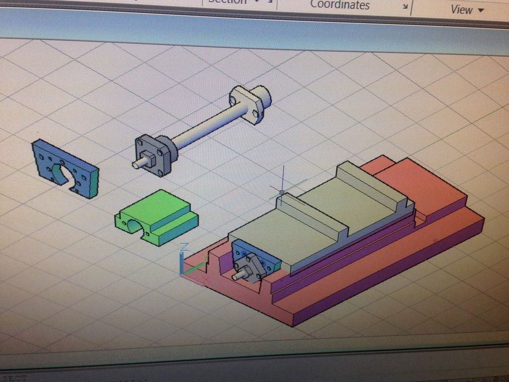 The two bits I need to make are the green block for the ball nut and the blue plate for the ballscrew flange, I just need to convert the model to 2d and then machine them out and I should have a "kit of parts" that I can bolt right on. |
|
|
|
Post by Roger on Nov 28, 2015 18:18:45 GMT
What have you used for the thrust bearings on the end? They ought to be a pair of angular contact bearings back to back really.
|
|
|
|
Post by Doug on Nov 28, 2015 19:16:45 GMT
They are the real deal I have used a THK BK10 bearing block no point messing around with the wrong bits if I am going to the trouble of swapping out to ball screws
|
|