lennart
Involved Member
   Currently building a Kennion's Chub as a first steam loco
Posts: 74
|
Post by lennart on Oct 1, 2019 18:17:24 GMT
Hello everyone,
it has has been some time since my introduction, but now with the E69 taking shape an nearing completition, it is time to start some serious thoughts on the next project. The progress of the E69 could be seen there: forum.zerspanungsbude.net/viewtopic.php?f=34&t=38217
As pointed out in the introduction thread my first project to show here will also be my first steam locomotive. I have chosen to build a Kennion's Chub because it is small, simple and doesn't have a specific prototype so modifications in the outline are not that critical. I got the drawings last autumn and the castings early this year.
 Chub steam loco (1) by Technikfreak L, auf Flickr Chub steam loco (1) by Technikfreak L, auf Flickr
Because I live in Germany, my machines, handtools and materials are in metric, so the drawings had to be converted to metric. Fortunately I have access to a CAD program so the whole redesigning was much easier. But I made also some more or less significant modifications, some of them can already be seen here on the screenshot and on the GA-drawing.
 Chub Inventor 4 by Technikfreak L, auf Flickr Chub Inventor 4 by Technikfreak L, auf Flickr
 1_Baugruppe Chub by Technikfreak L, auf Flickr 1_Baugruppe Chub by Technikfreak L, auf Flickr
Starting with the running gear, I modified the axleboxes to the split type to make life easier, when the day comes to replace them. The big end bearing of the eccentric rod will be an ball bearing, like on the BR Standards, but with a much less fancy housing. The expansion link as original designed was also of the BR Standard type with the pivot pins attached to the link with two small brackets. I don't know, what Charles Kennions's thoughts were about this, but the expansion lik would have fouled it's bearing, so I changed it to the LNER type (like i.e. on the B1s)with two plates attached to the front and rear of the expansion link to clear the bearing.
I didn't change the geometry of the valve gear. From my understanding the valve events are quite good. But if someone would like to check this, I would be happy, too. I could email the relevant drawings.
Up to the boiler. Most of the other members of my local society have built their locomotives without a superheater or removed it, because it didn't make any difference in power or economy and they had the ever lasting problem of blocked tubes. To avoid the hassle with blocked superheater tubes and a crowded smokebox (wich is very small in the first place), I won't fit superheaters either. So the boiler's tube layout has to be changed to fluetubes only. You might have seen, that the Boiler is still empty on the drawing.
I will go into greater detail, when the build has progressed eventually to these stages.
To make a start on the build and to make life easier I think about getting the frames and some parts of the valve gear waterjet cut. For the electric locomotive I ordered some laser cut parts but the tools, especially the small files and milling cutters struggeled with the hard surface. The distortion was also much worse than I would have liked.
Do you have more experience with warerjet cutting in regard to surface finish, distortion and accuracy, than myself? At least some of you would, I think. Next stage would be (if the valve gear doesn't need further attention) to get the DXFs exported from the parts. I will of course add some allowance to the surfaces, that need further machining, like on ther cutouts for the horns in the frames, but are there other things, that I have to keep in mind?
|
|
|
|
Post by Roger on Oct 1, 2019 20:28:34 GMT
I've just taken a look at your YouTube channel, your electric locomotive makes light work of that extensive track! I wish there was one like that near to me. It's an excellent idea to model the project like you've done, that's how I found the initial errors in the plans for my build, ending up with completely redesigning almost everything. It going to be a really nice little locomotive, very pleasing to look at and not too hard to make. I wonder what Superheaters your club members were using before abandoning them, I suspect they were not Radiant types which certainly do make a difference. Still, I can see why you might not want the extra complication, and it will definitely work well enough without them. I'd be a little cautious when accepting advice on Superheaters from people who haven't got experience with Radiant types though. Do Model Engineers in Germany use other Mainland European suppliers other than Knupfer? That's the only one I've found and used for my Metric nuts and bolts. There was another one I've seen, but they seem to have stopped trading. Anyway, I very much look forward to seeing your build in progress. P.S. Out of interest, this is a very informative video about Water Jet cutting which explains everything you need to know. The tilting head is used to get rid of the taper on the part, so that ought not to be an issue. |
|
|
|
Post by steamer5 on Oct 1, 2019 20:35:46 GMT
Hi Lennart,
Have a chat to your Waterjet guy about any allowance. I had some done nearly 20 years ago for the motion work & they have a distinct taper on them. Stuff I had done in the last year or so doesn’t. The parts are from 2 different suppliers, ( in 2 different countries) but that aside the technology has moved on. The local guy has a 2 1/2 axis machine, the 1/2 axis allows for the machine to make allowances for the thickness of the material & hence no taper. As to machining allowance a chat to your guy & maybe a test part to see maybe a good idea, you may very well find that a quick file is all you will need.
As a indication of how good the size / finish is I had 3 quick change tool holder tool blocks cut from my own drawings after measuring up from my others & they fitted with no finishing required!
Hope that helps
Cheers Kerrin
|
|
|
|
Post by David on Oct 2, 2019 5:26:33 GMT
I have had frames and hornguides waterjet cut and was able to use them with no work required at all. We asked for the important bits to have a better tolerance than the rest, and that increased the cost quite a lot.
Water jet cutting gives an excellent finish and no distortion or hardening that I could notice, but it's really expensive down here.
Looking forward to watching your build.
|
|
lennart
Involved Member
   Currently building a Kennion's Chub as a first steam loco
Posts: 74
|
Post by lennart on Oct 5, 2019 19:36:41 GMT
Do Model Engineers in Germany use other Mainland European suppliers other than Knupfer? That's the only one I've found and used for my Metric nuts and bolts. Thank you everyone for your encouragement.
I will contact a waterjet cutting company shortly to ask them, what they think about the project. As far as I have done my research, modern waterjet cutting machines can compensate for the tapered cut, so, as Kerrin said, that should not be a problem.
Knupfer supplies basically nuts, bolts, springs and other small functional and non functional locomotive parts.
There are some other suppliers for steam fittings, bar stock, castings and drawings, etc. some of them focus on stationary engines, some on locomotives.
www.modellbau-niggel.de/
www.bengs-modellbau.de/
www.ts-modelldampfmaschinen.de/
just to show the ones ones I know the best.
So there are quite a few suppliers for small parts but, much less than in the Uk of course. I only know two boilermakers, one builds only for people, he knows personally and both make stainless steel boilers only. So copper boilers have to be made by the builders themselves or bought in the Uk. Propably one reason, why most larger model locomotives over here have welded steel boilers.
|
|
|
|
Post by Roger on Oct 5, 2019 20:56:02 GMT
Do Model Engineers in Germany use other Mainland European suppliers other than Knupfer? That's the only one I've found and used for my Metric nuts and bolts. Thank you everyone for your encouragement.
I will contact a waterjet cutting company shortly to ask them, what they think about the project. As far as I have done my research, modern waterjet cutting machines can compensate for the tapered cut, so, as Kerrin said, that should not be a problem.
Knupfer supplies basically nuts, bolts, springs and other small functional and non functional locomotive parts.
There are some other suppliers for steam fittings, bar stock, castings and drawings, etc. some of them focus on stationary engines, some on locomotives.
www.modellbau-niggel.de/
www.bengs-modellbau.de/
www.ts-modelldampfmaschinen.de/
just to show the ones ones I know the best.
So there are quite a few suppliers for small parts but, much less than in the Uk of course. I only know two boilermakers, one builds only for people, he knows personally and both make stainless steel boilers only. So copper boilers have to be made by the builders themselves or bought in the Uk. Propably one reason, why most larger model locomotives over here have welded steel boilers.
Thanks for the links, I've made copies of those. I was hoping to find a supplier of reduced head M1 nuts and bolts, but so far the only ones I can get are Brass and pretty hopeless. I'm beginning to think that they simply aren't available and I'll have to make my own if I want them that badly. |
|
|
|
Post by steamer5 on Oct 5, 2019 22:16:06 GMT
Hi Lennart,
I forgot to mention re the watercutting, it’s time on the table that cost! So thicker material cost more to cut per linear dimension than thin.
The tool holders I had done the guy pointed this out as I took the blocks of steel with me....so I headed home & machined them before cutting rather than after which had been the plan
Cheers Kerrin
|
|
lennart
Involved Member
   Currently building a Kennion's Chub as a first steam loco
Posts: 74
|
Post by lennart on Nov 3, 2019 19:00:21 GMT
Not too much has happened since my last post.
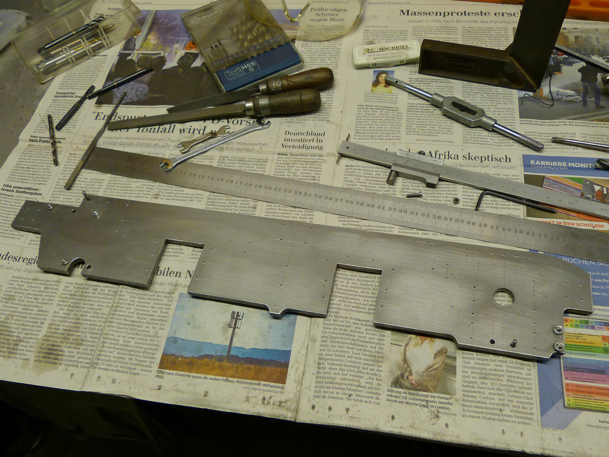
I collected the waterjet cut parts yesterday and had a lokk at them today. They had much less rust on tzhem than expected, a little bit on the cut surfaces but almost none at all on the rolled surfaces. The frames an the reverser stand are cold rolled 3mm material and the rods nad the guard iron were cut from 5mm, 8mm and 10mm hot rolled steel sheet.
 Chub steam loco (2) by Lennart Glauche, auf Flickr Chub steam loco (2) by Lennart Glauche, auf Flickr
The parts only have their basic profile cut. I will drill the holes in the frames by myself. The same for the rods. The exact spacing of the holes will be carried out on the mill for the highest accuracy. Only the Expansion links have their contour fully cut. I ordere them in the highest possible accuracy that I can get around machining the curved solt. Hopefully... The eccentric rods got an elongated small end instead of the round one, so that the final spacing of the holes could be adjusted.
The first parts to be machined will probably be the buffer beams and buffer beam angles. I got some 25x25x4mm cold rolled angle Iron, that should be square enough without machining it. Is this already sufficient, or should the angles be machined anyway? I will deviate from the drawing by adding a stiffening plate (Does this par have a specific Name?) betwen the drawhook and the buffer beam. The Bufferstocks will also be altered to be a little bit closer tro prototype.
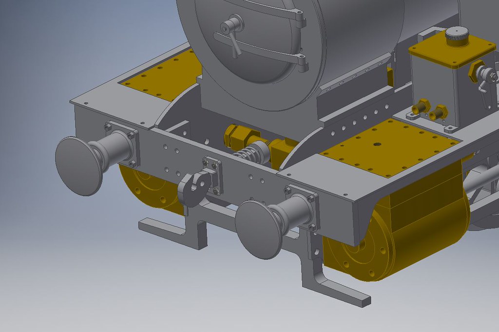 Chub Inventor 5 by Lennart Glauche, auf Flickr Chub Inventor 5 by Lennart Glauche, auf Flickr
So, hopefully there will be some progress soon.
|
|
lennart
Involved Member
   Currently building a Kennion's Chub as a first steam loco
Posts: 74
|
Post by lennart on Nov 6, 2019 19:24:11 GMT
When thinking about the buffer beam angles, I found three possible ways to drill the holes into the angles, the buffer beams and the frames. The holes for the bolts to connect the angles to the frames have to be drilled separately anyway. But for the buffer beam they could be either transferred from the buffer beam to the angles or the other way around or drilled seperately on the mill.
I don't have an own milling machine, but have access to milling machines, one with an DRO at our club workshop. So coordinate drilling by the DRO should give accurate results, too. Since the angles are supposed to be fitted by bolts and not by rivets, the perfect alignment should not be that critical. So drilling M3 clearance holes gives a little room for adjustments.
Every method may have it's advantages and disatvantages, but is threre one, that should be used on the confined space on the chub? Any suggestions?
|
|
|
|
Post by Roger on Nov 6, 2019 23:29:33 GMT
I'd certainly use the machine with the DRO, it's way easier to get things really accurate. Hopefully you have a wobbler that will find the edge really accurately. I would avoid spotting through, only using it as a last resort. If you machine it with the DRO, it should fit perfectly. I can't remember the last time I spotted anything through.
I'd drill the M3 clearance holes at 3mm, the closer the fit and the less adjustment the better in my opinion. You won't need adjustment if you make it really accurately.
|
|
lennart
Involved Member
   Currently building a Kennion's Chub as a first steam loco
Posts: 74
|
Post by lennart on Jan 3, 2020 19:31:05 GMT
It has been a while since my last post.
But since then I actually built something. I made a start on the buffers. The design deviates from the Kennions drawing quite a lot. The bufferstocks are a little bit closer to the full size layout instead of plain cones. The heads are fixed by a M5 nut from behind instead of a tiny pin through a slot in the stocks. Machining was strait forward. The only thing I should mention is how I faced the rear of the bufferstocks. They were turned from bar stock and partet off a little oversize. To hold them securely I put three shaft keys between the part and each chuck jaw to clear the beading at the front. The picture shoud make this clear.
Then, I went over to the frames.
As Roger recommended I drilled the M3 clearance holes for connencting the buffer beams and angles to the frames on one of the club's milling machines.
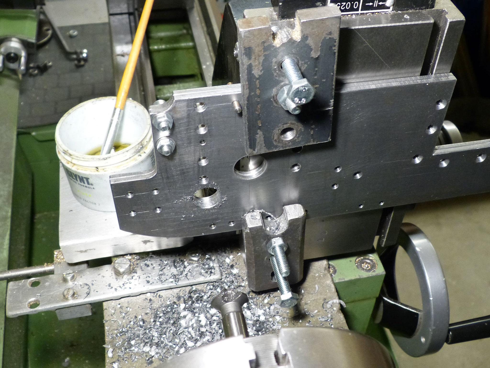
I didn't take the frames to the club, so they were drilled after lots of marking out and center punching. Two holes were reamed and fittet with pins to make sure that they don't move relative to each other and can be put back together accurately between the several stages of drilling and tapping. The 14mm hole for the steam ches union was drilled on the lathe becaus this was above the capability of my small drill press. It was not cit out by the water jetting company, becaus I was not sure about its position when I placed the order.
Finally I made a first trial assembly. As expected, Everything fits nicely and square.
The hornblocks will be the next parts to think about. They are cast in pairs to simplify maching. I already faced them to length on both the outside and inside to get some datums to measure from.
The cutouts in the frames were waterjet cut, so they vary in width by a few thou. I would suggest to mill the horns to fit each cutout individually and mark them respectively. The already drilled holes in the frames can then be spotted through and drilled clearance size for M3 countersunk screws. Or is it a bad idea to bolt the horns to the frames instead of using countersunk iron rivets? I think threading the casting for the M3 screws is not an option, because the casting is too thin toget onough threads in there (about 3mm).
Then the frames are clamped back to back and the insides of the horns can be milled to size.
|
|
lennart
Involved Member
   Currently building a Kennion's Chub as a first steam loco
Posts: 74
|
Post by lennart on Feb 13, 2020 14:14:18 GMT
I have made some large steps forwad since my last post in January. The first part to be machined this year was the pump stretcher. As you might have noticed on the drawing in the first post, the axlepump has to be squeezed in a very confined space between the firebox an the leading axle. So the stretcher is a little bit off-standard, too. I started machining by holding it in the 4-jaw by two jaws only and facing the rear face. The bolts were put inbetwewn the jaws to avoid the casting being bent.  Chub steam loco (9) Chub steam loco (9) by Technikfreak L, auf Flickr With that first face accurately machined, the stretcher was clamped onto the faceplate by thwo improvised clamps and got the mounting face for the pump machined flat. The "legs" were also turned to final length in this setting.  Chub steam loco (10) Chub steam loco (10) by Technikfreak L, auf Flickr The top and underside were faced with a large homemade flycutter with the casting clamped to an angleplate on my lathe's cross slide. This worked surprisingly well.  Chub steam loco (11) Chub steam loco (11) by Technikfreak L, auf Flickr The most importand step was to accurately mill the width to 105mm so that it will sit between the frames without binding or wobbling about. This was done in the vice on the vertical milling slide. In the same setup I milled the insides of the legs to give a flat surfavce for the bolts to sit on (on picture).  Chub steam loco (12) Chub steam loco (12) by Technikfreak L, auf Flickr The last things to be done were the holes for mounting the stretcher in the frames. These 6 screws will also hold the motion plates on the outside. Next parts to be shown are the horns. I will write about their machining shortly. |
|
lennart
Involved Member
   Currently building a Kennion's Chub as a first steam loco
Posts: 74
|
Post by lennart on Feb 16, 2020 12:51:18 GMT
The hornblocks were machined next. You have seen this probably 1000 times before, but I will show you my approach wich might be a little different. The castings were already machined to final thickness in December last year. It was very convenient that they were cast in pairs so they could be clamped in the 4-jaw. The screw prevents the casting from being bent, just like the pump stretcher.  Chub steam loco (13) Chub steam loco (13) by Technikfreak L, auf Flickr The face wich will be on the inside later was faced first to take as much as possible off from this side. Then the flanges will be as thick and as stiff as possible.  Chub steam loco (14) Chub steam loco (14) by Technikfreak L, auf Flickr A simple fixture was made to clamp the split hornblocks onto the milling machine to cut the recess to sit in the frames. The rear horns have most of their upper part removed to clear the firebox. It will sit just above the cut outs in the frames so that there will be no room for the hornblock's flange. These portions were milled away first. I removed the castings from the fixture afterwards to check for distortion after removing that much material. Luckily there wasn't much distortion so they could be staightened in a few minutes.  Chub steam loco (15) Chub steam loco (15) by Technikfreak L, auf Flickr The other pair was machined in one setup to fit the frames as there wasn't as much material to be removed.  Chub steam loco (16) Chub steam loco (16) by Technikfreak L, auf Flickr Back at home I clamped each hornblock to it's cut out and transferedrilled the holes. After a lot of thinking I decided to tap the Horns and use countersunk M3 screws instead of rivets as the flanges remained thicker than I first expected. There was about 4mm to 5mm left to be tapped. So there are about 8 to 10 threads in each hole wich should be sufficient. Or should I drill out the threads and use rivets instead to be sure that nothing will fall apart later? To mill the insides of the horns to size I chose to use our club's Deckel FP2 wich is still the most accuarte one of the milling machines there. A large angle plate came in very handy to stiffen the setup. It was not as rigid as I would have liked, but with small cuts and feed rates it worked out very smoothly. Unfortunately the smartphone focussed on the angle plate and not the interesting parts. 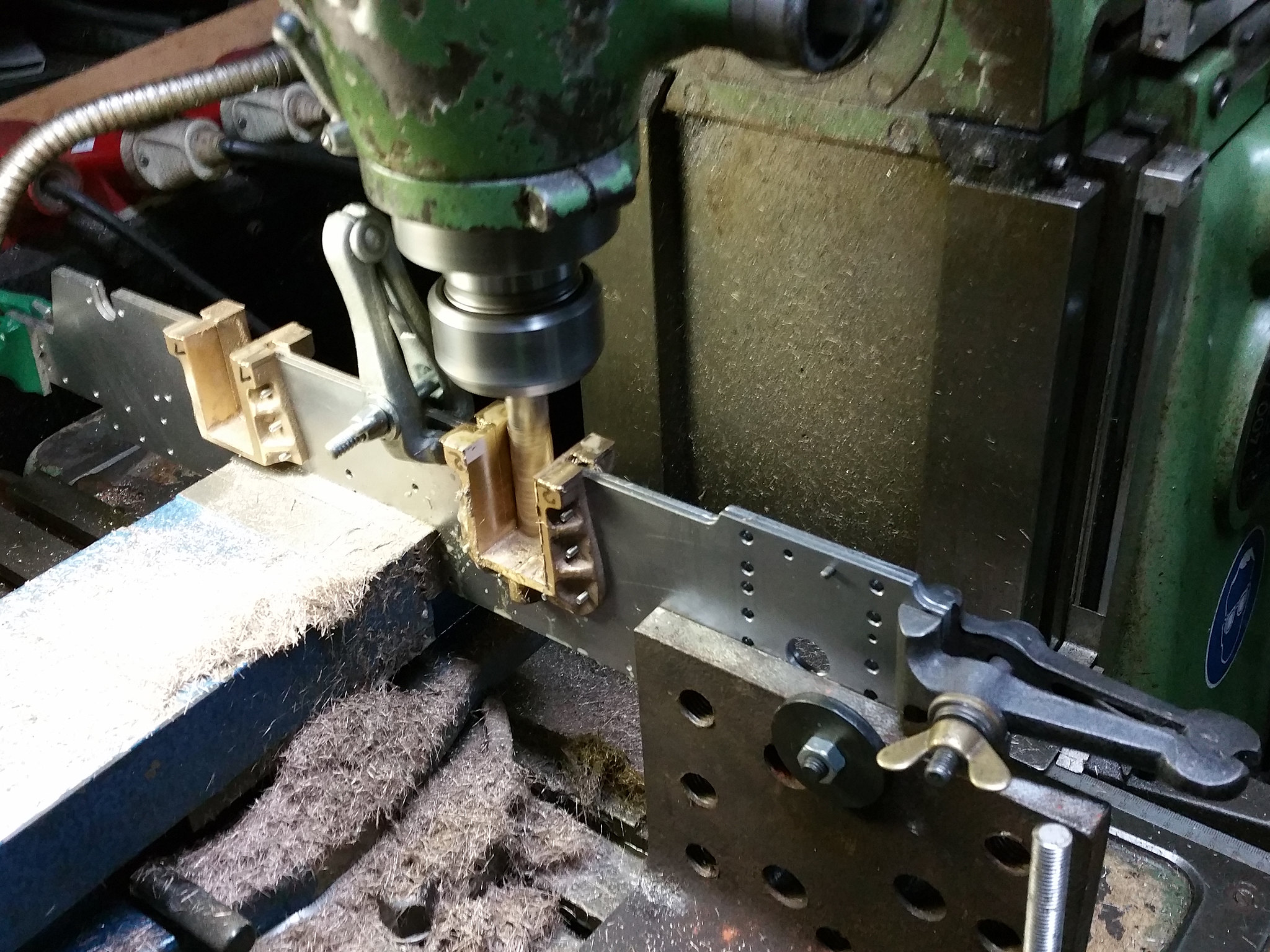 Chub steam loco (17) Chub steam loco (17) by Technikfreak L, auf Flickr After the first cutout was finished, the angle plate was moved to the other side and I checked that the frames haven't moved. Since the wheelbase is only 159mm the frames didn't need to be moved.  Chub steam loco (18) Chub steam loco (18) by Technikfreak L, auf Flickr I checked the size with a 32mm slip gauge wich could be pushed into the slots with minimal effort but didn't fall right through. So I guess that I hit the 32mm pretty much spot on. Last thing to be done was a trial assembly of the frames with the horns and the pump stretcher.  Chub steam loco (19) Chub steam loco (19) by Technikfreak L, auf Flickr |
|
|
|
Post by David on Feb 17, 2020 6:28:57 GMT
Good result. :)
I'm wondering if with the openings so precise to 32mm you're going to find binding a problem due to slight misalignments after bolting on the buffer and drag beams and the pump stretcher! Anything other than fitted bolts and CNC drilled holes is going to have some leeway.
Plus you need some room for the oil.
But you're on the right side of the problem, if there is one.
|
|
rrmrd66
Part of the e-furniture

Posts: 339 
|
Post by rrmrd66 on Feb 17, 2020 8:26:59 GMT
Hello Lennart
Ausgezeichnet!
Good work and excellent photographs. Sharp, in focus and well lit.
Keep up the good work.
Cheers
Malcolm
|
|
dscott
Elder Statesman
  
Posts: 2,440
|
Post by dscott on Feb 18, 2020 0:24:03 GMT
Yes superb work and the lighting perfect.
I tend to use lighting for all my workshop shots which end up in the Club Magazine.
Yes too many projects but if one develops a problem I have another to undertake while it is solved.
Chub in Metric is such a great idea. I tend to reach for the other side of the ruler when drawing something out.
Best regards from the Reading Society England.
David and Lily.
|
|
lennart
Involved Member
   Currently building a Kennion's Chub as a first steam loco
Posts: 74
|
Post by lennart on Feb 18, 2020 19:44:43 GMT
Thank you for your kind comments. I machined the slots to 32,00mm so the axleboxes were machinde a little bit under size to allow for misalignment and the other built up tolerances. As you might have expected, I made the axleboxes next. I chose the split type to be able to machine a recess into the lower part as an oil reservoir and to make life easier when it comes to renewal. They started with two blocks of gunmetal, that was squared up and reduced to the requiered dimesnion of 38 x 20,5mm. I did this on the lathe at home becaus there was nobody at our club that day.  Chub steam loco (20) Chub steam loco (20) by Technikfreak L, auf Flickr At the weekend I came to the club to make all the precision work. First the recesses to fit into the horns were milled. I left them pretty tight to be able to increase the play and not to directly end up with a rattle fit. How much smaller should the axleboxes be than their slot? Is a play of 0,03 to 0,05mm acceptable to allow for misalignment, tolerances and thermal expansion?  Chub steam loco (21) Chub steam loco (21) by Technikfreak L, auf Flickr The blocks were then split in to 8 parts that were milled to the requiered thickness afterwards. I always kept an eye on the squareness.  Chub steam loco (22) Chub steam loco (22) by Technikfreak L, auf Flickr At home I coordinate-drilled the holes for the spring pins and 4 holes for fixing the upper half to the lower. The countersinks were cut with a 6mm endmill. The Chub uses the conventional suspension layout with two coil springs for each axlebox.  Chub steam loco (23) Chub steam loco (23) by Technikfreak L, auf Flickr Then each half finished axlebox was assembled for the first time. No.2 has been bored already. 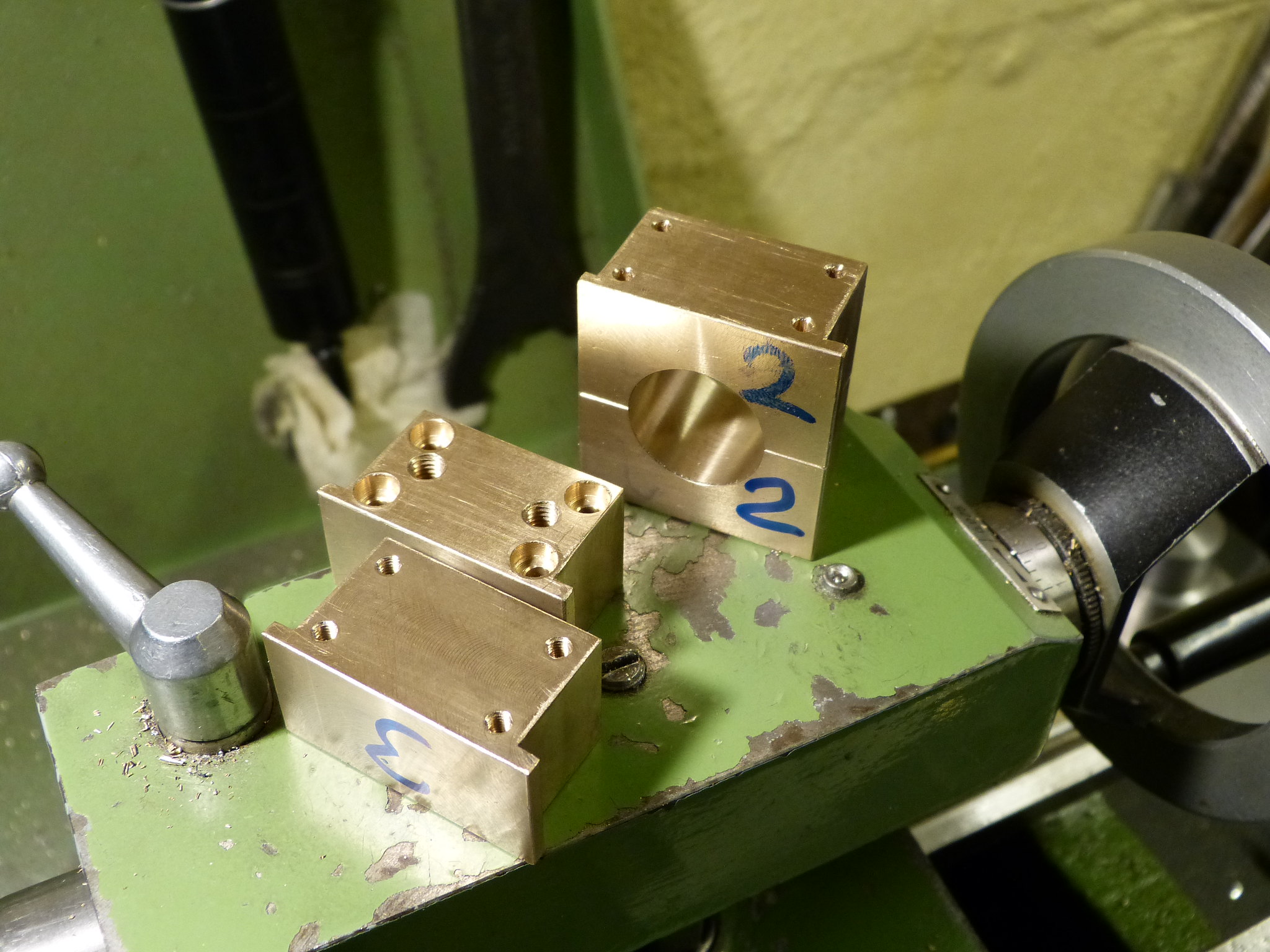 Chub steam loco (24) Chub steam loco (24) by Technikfreak L, auf Flickr I didn't make any fancy fixture for holding them in the lathe. Instad I carefully clamped them in the four jaw chuck. The room between the jaws and the flange at the front was just enough to reach inbetween with a dial indicator. I ended up with about 0,01mm difference on the sides and started boring. I started with several Twist drills and bored to 20mm with a very sharp HSS boring bar that I only use for those critical operations. As I don't have a DRO on my lathe and the dials were not precise enough, I made a simple dial indicaltor holder some time ago.  Chub steam loco (25) Chub steam loco (25) by Technikfreak L, auf Flickr With all axleboxes bored I tried them into their slots in the frames.  Chub steam loco (26) Chub steam loco (26) by Technikfreak L, auf Flickr As expected, they are a little tight, but two ground silver steel shafts fittet already through without binding. I didn't want to free them off before I read some of your recommendations for the play in the hornblocks. So the oil reservoirs will be next. |
|
|
|
Post by Deleted on Feb 18, 2020 20:39:35 GMT
Great work Lennart..split axleboxes are worth the extra work...nice job...
Pete
|
|
lennart
Involved Member
   Currently building a Kennion's Chub as a first steam loco
Posts: 74
|
Post by lennart on Mar 31, 2020 9:36:35 GMT
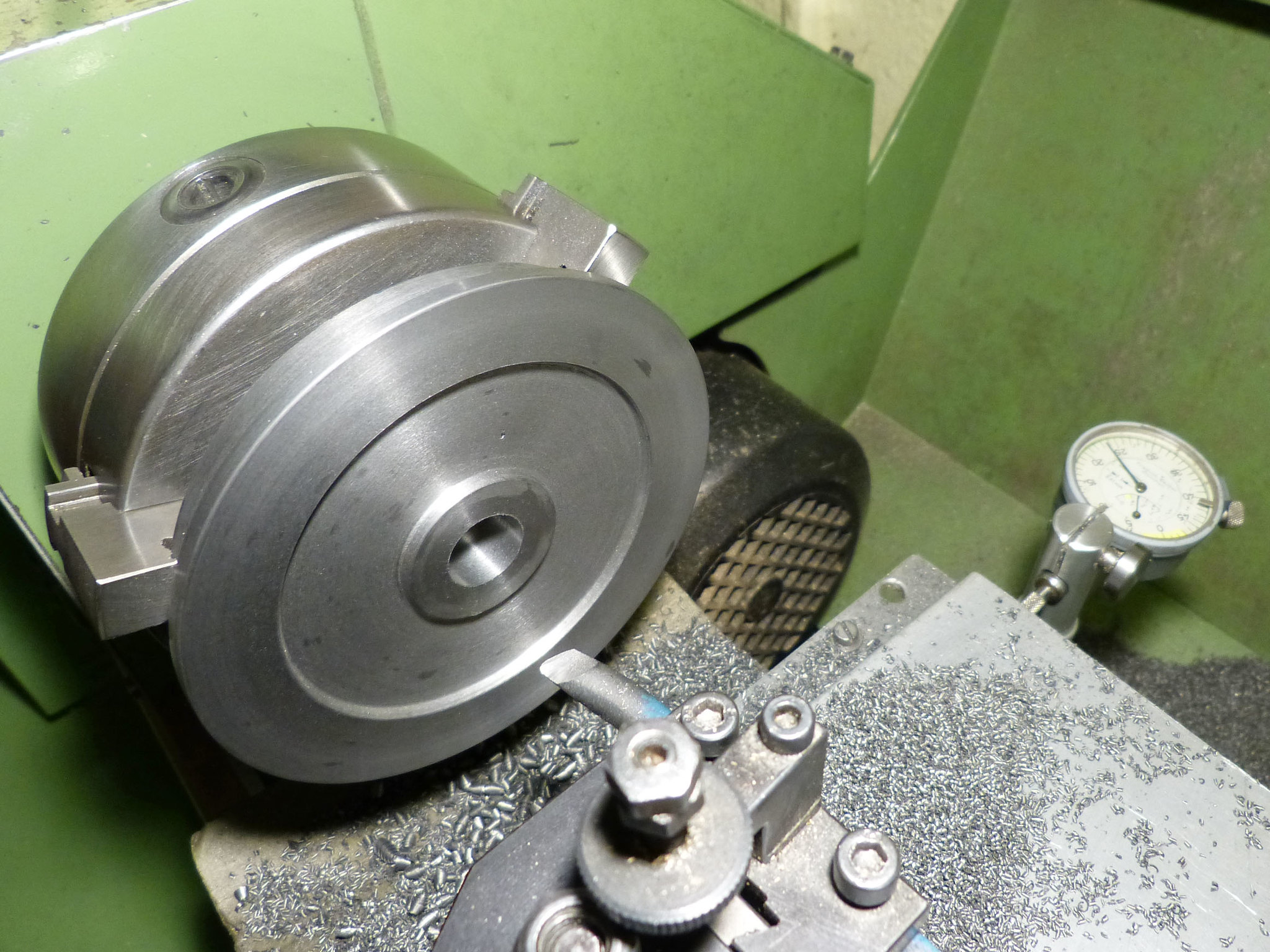
Like most of you, I have more time to spend in the workshop than usual. So I'd like to show you how I approached the wheels. I clamped them by the flange, adjusted them to run reasonably true and took some light cuts on the tread and the face to get rid of the cast surfache. I had my vacuum cleaner running all the time to prevent the fine cast iron dust from flying everywhere. The indicator stand came in very handy but I removed it when the following pictures were taken.
The casting was then reversed and clamped onto the newly machined surface. That made sure that the hub and spokes run true when the rear is machined, since they can be barely seen in this setup.
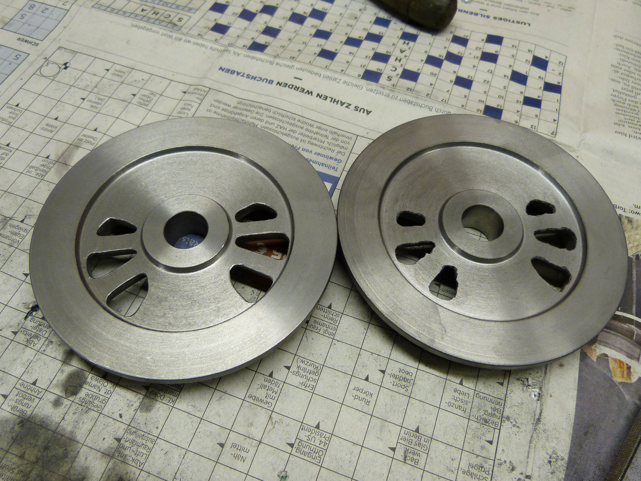
As you might have seen in the first post, the spokes were not cast in at full depth. So there was a about 3mm thick solid portion on the rear face, that was machined away. I just turned it as deep as necesarry, until the first space between the spokes just broke through (12 o'clock position above) and removed the remainding material with a chisel.
Then reversing again to machine the rim, hub and counterweiht to final thickness.
To finish the tread and flange to final size I made a simple fixture out of an aluminium disc, that locates the wheel by it's bore. The bolt between two spokes acts as the driving pin. All four wheels were then turned in one setup.
The chamfer and the small grove between the rim and the counterweight were machined afterwards, since their concentricity is not that critical at all.
This is the amount of cast iron, that did not make it into the vacuum cleaner. The total volume of chips is about twice as much, I'd guess.
Last operation was to drill and ream the crankpin holes. The drawing calls for a 1/2" bore and a plain 1/2" pin without any shoulder to fit into the wheel. I don't think that is a good way of doing it so I decided to use 12mm unhardened silversteel and to turn it down to 10mm to fit into the wheels. I plan to finally fit hem with loctite 603. So the wheels were reamed 10mm instead of 1/2". I clamped the ficture to the vertical slide, clocked it true and moved the cross slide by the crank throw. This should have given me the best accuracy.
The machining itself didn't show any difficulties.
The axles were turned next. Some plain turning, wich doesn't need a picture. I machine the 20mm stock down to 16mm to fit into the weels. The axles are 0,01mm smaller than the holes to give some room for the loctite.
Now, I've got a rolling chassis. Well sort of, because the wheels are still lose on the axles and wait to be quatered. I still have to think about the best way to pin them together afterwards. I will probably go the way to fit pins axially between the axle and the wheel, but how can I prevent the drill from wandering straight into the cast iron? Milling a round grove with an ball nose nedmill into the silversteel is not an option, since I have netither a suitable endmill nor a dividing head.
|
|
stevep
Elder Statesman
  
Posts: 1,073
|
Post by stevep on Mar 31, 2020 10:50:49 GMT
I built my Rob Roy over 40 years ago, but I pinned the wheels to the axle (after Loctiting the wheels on) by drilling axially along the joint line. I don't remember the drill wandering off - and quite frankly, provided when you start you are in both parts, you will achieve the aim of them not moving.
|
|
 Chub steam loco (1) by Technikfreak L, auf Flickr
 Chub Inventor 4 by Technikfreak L, auf Flickr
 1_Baugruppe Chub by Technikfreak L, auf Flickr


