|
|
Post by NSWGR Steambuff on Dec 10, 2014 9:21:39 GMT
Hello John,
Thanks for the reply. I am reasonably comfortable with machining the rod ends and using a stop to get an accurate stop for each pass, but my main concern is getting an accurate flute profile . The flutes on one pair of coupling rods and the connecting rods are tapered. The other pair of coupling rods (front rods) require a parallel flute.
My dilemma is trying to find a suitable cutter to achieve a flute with nicely rounded edges, rather than using a square edged cutter like a slot cutter or woodruff key.
Cheers,
Ned
|
|
|
|
Post by Deleted on Dec 10, 2014 9:27:46 GMT
Hi Ned
If I understand you correctly a profile cutter may not be necessary. I softened the flute edges using nothing more complicated than emery cloth. That worked in 3.5" but perhaps not in the larger sizes.
John
PS I've added another link!
|
|
|
|
Post by ejparrott on Dec 10, 2014 9:52:48 GMT
If you're thinking of the root radius of the fluting, you can get cutters with a rad on the corners, but I think you'd either have to have a woodruff specially ground, or go to a side and face cutter on a horizontal axis
|
|
|
|
Post by Jim on Dec 10, 2014 11:27:36 GMT
depending on the style of fluting I used a small ball nosed cutter to form the fluting on Boadicea's rods. 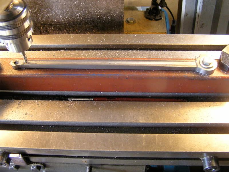 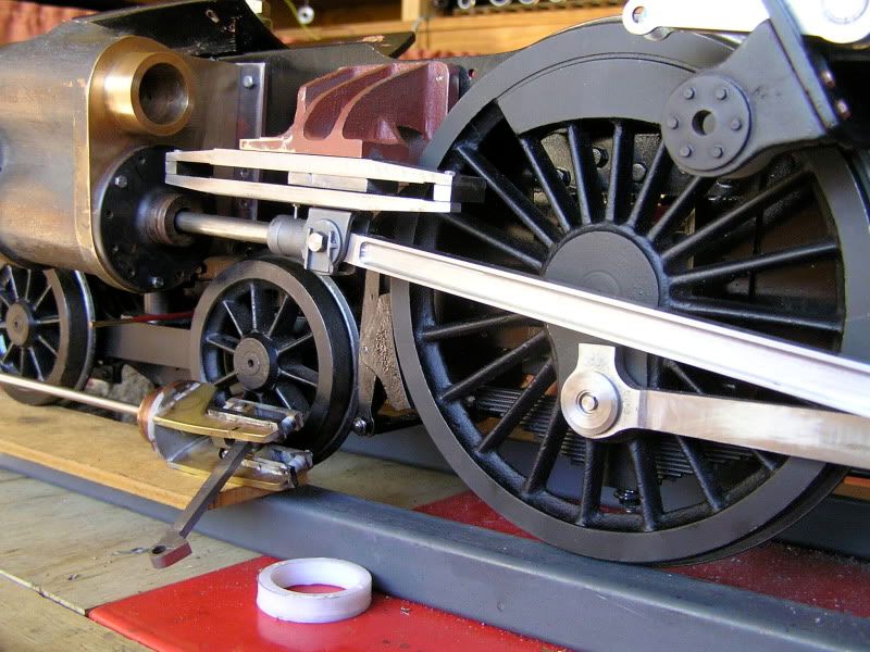 Jim |
|
|
|
Post by Roger on Dec 10, 2014 12:01:51 GMT
Jim's setup is very similar to the way I did mine on the CNC. You can get ball nosed cutters of any diameter to get whatever radius you want, you just have to take small cuts and be very gentle. I bought mine from eBay with 2mm diameter ends. Since I was using CNC, I used the same cutter to remove all of the material too but you won't want to do that manually.
|
|
|
|
Post by ettingtonliam on Dec 10, 2014 13:05:50 GMT
If you're thinking of the root radius of the fluting, you can get cutters with a rad on the corners, but I think you'd either have to have a woodruff specially ground, or go to a side and face cutter on a horizontal axis A while back I got a job lot of woodruff cutters for not much money, so sacrificed one by freehand grinding a small radius on the tips of the teeth. Not very precise, but it does produce flutes with radius roots that look the part. |
|
|
|
Post by Jim on Dec 10, 2014 17:14:46 GMT
Jim's setup is very similar to the way I did mine on the CNC. You can get ball nosed cutters of any diameter to get whatever radius you want, you just have to take small cuts and be very gentle. I bought mine from eBay with 2mm diameter ends. Since I was using CNC, I used the same cutter to remove all of the material too but you won't want to do that manually. Actually I did much the same as Roger did with his CNC machine. I marked out the rod with the outer limits of the flutes first then I marked the inner lines indicating the centre point of the cutter. I used a laser edge finder to line the job up to ensure the cutter would track along the inner line then set the stops on the milling table for the ends of the fluting and away I went. Once I'd done one edge to the required depth I the started removing the waste until I got close to the other side. Then using the laser edge finder the job was re aligned and the stops re adjusted. Care is obviously needed in bringing the cutter back down to the same depth as the previous cuts but taking it gently it can be done.  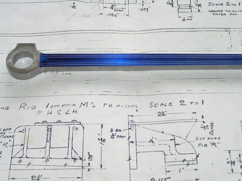 Jim |
|
|
|
Post by NSWGR Steambuff on Jan 11, 2015 4:32:06 GMT
Firstly my belated thanks to those replied with advice on doing the rods. I finally decided to do them with a ball nosed end mill. 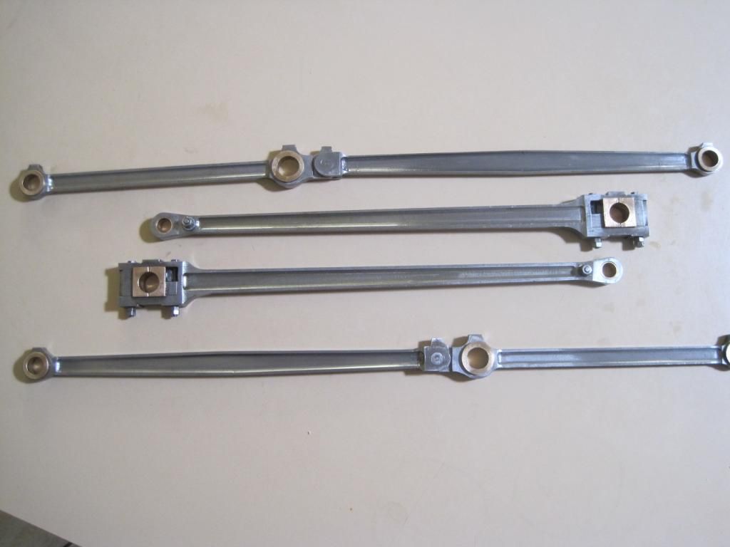 I have made a bit of progress and built a rotating stand to make building a little easier. 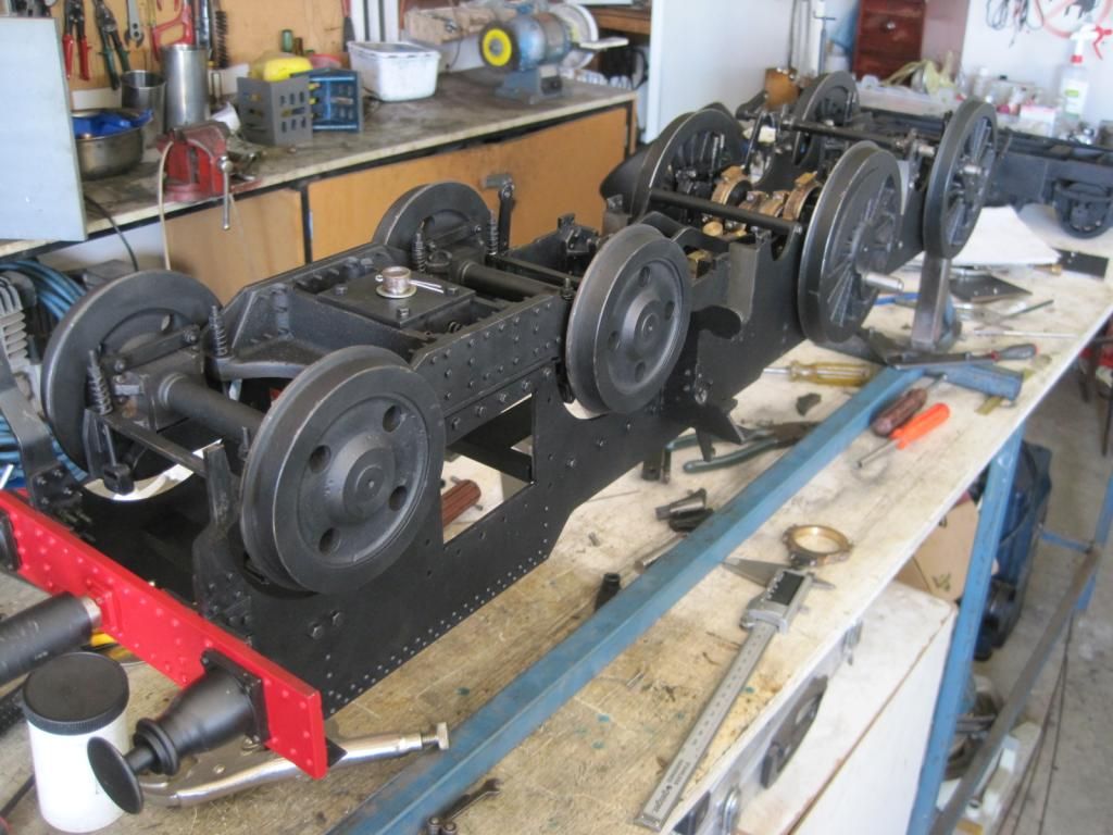 I have just fitted the valve eccentrics and gear and seem to have run into a problem with the initial eccentric settings. I have not as yet machined the cylinders, so the radius rods are just fitted to complete the assembly of the valve gear. A pic of the plans may help. It uses the Allen straight link gear. 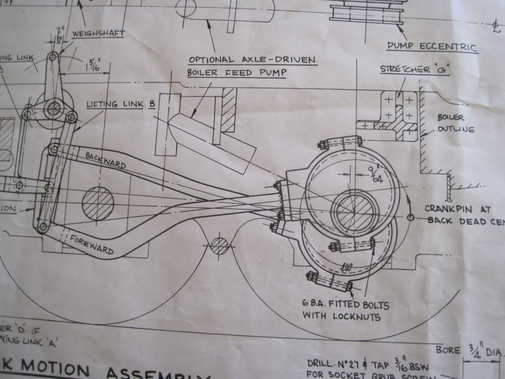 I have built so far exactly in accordance with the plans because I don't know any better, and this is my first loco build. I have set the eccentrics as per the plans above, but find that the gear is locking up at the point where the lower, or forward eccentric rod reaches it's rearmost position. It's as if the eccentrics are in the wrong position, but I have checked and double checked the settings. Any assistance especially from those who have built this type of loco would be appreciated. I am nowhere near any known builder of this loco so don't have anybody to ask, or indeed another completed example to look at. There may be an error in the plans for all I know. I am hoping Shawki, or anybody else who has built a loco with Allan straight link valve gear, may read this and enlighten me. |
|
|
|
Post by Shawki Shlemon on Jan 11, 2015 8:57:27 GMT
Is a while since I built this type ( 3 of them from the same designer ) , I can't recall any problems with it , they are very close fit , I would be looking for something touching or not enough room for die block going up and down , it is a straight link and not as easy flow like the Stevenson . I made two sets of valve gear when I was building SMR10 , one for the D50 and few years later I fitted them on the 50 without any problems , I am saying this to assure you the plans are OK , your problem is something simple , look carefully at the link and the die .
|
|
|
|
Post by suctionhose on Jan 11, 2015 10:08:01 GMT
I'm pleased Shawki replied because he would be one of very few that have completed a 32 to the EJW design.
Most of the Allen gear engines running in 5" are built in 1 1/8" scale from NSWGR drawings or have a version of the gear devised by persons other than EJW.
In full size the 50 class and the 32 class had different versions of Allen. My own 50 class was scaled from full size drawings with pertinent checks to ensure the valve did the right thing at the right time.
I suggest that you could do the same with the EJW design once the mechanical issues have been sorted.
In terms of the eccentric settings, Allen doesn't differ all that much from Stephenson's. The main difference being the straight Link and the combined raising of Link with lowering of valve rod which allows the straight slot to follow the approximate track required for the die block. The was also the likely advantage of operating with low head height as with the 50 being a goods 2-8-0 with only 4' 3" drivers.
In reality the 32's or P class as there were classified in 1892 had pretty ordinary valve events. Any archival sound film will confirm this as will the preserved 3265. Full gear is OK but they don't notch up very well. The 50's were better as were the 30 class tanks but no version of Allen comes close to a well designed set of Stephenson's.
You may be interested to know the P class (later C32) was introduced by the newly appointed CME of NSWGR, Mr William Thow. Turns out Mr Thow was Mr Allen's protégé so one might surmise the Royalties from use of Allen's Patents on 700 new locomotives in NSW was a fitting payback by Thow to his Mentor. Probably kept him warm and comfortable in his declining years!
|
|
|
|
Post by NSWGR Steambuff on Jan 11, 2015 10:54:09 GMT
Thank you for the prompt reply Shawki. I will pull it all apart again and have a closer look at the link and die block.
Ross, thank you also for your comments.
An interesting insight into the history of the use of Allen valve gear on Mr. Thow's locomotives.
I have done a bit of reading on early NSWGR locomotives and got the impression that the Allan gear was not as good as the Stephenson. My early stage of learning about building a model however, meant that I had to initially follow a set of drawings, and that, together with the fact that the prototype also used this system, led me to where I am at.
Your statement "I suggest that you could do the same with the EJW design once the mechanical issues have been sorted", has me interested.
When you get the time would you mind expanding on that a little??
Thanks again to both Shawki and yourself.
Ned
|
|
|
|
Post by Deleted on Jan 11, 2015 11:31:13 GMT
What is the origin of the full size engines - are they standard 'colonial engines' as supplied by Beyer Peackock , Dubs , North British etal or are they NSWGR manufacture ??
Thanks
michaelw
|
|
|
|
Post by suctionhose on Jan 11, 2015 11:42:04 GMT
Ned,
What I mean is that in running position you want the valve to open at beginning of stroke and close again at roughly the same piston displacement for all 4 strokes.
Having made all the parts to a drawing, you are beyond the point of "designing". Put it together and see if it "does what you want".
The basic checks on assembly are:
1. On dead centre move from full fwd to full rev. The valve should return to same position ie. Cracked open by lead. If not correct eccentric rod length.
2. Position valve on spindle so same occurs at any of the 4 dead centres.
If it doesn't then head scratching begins!
I have to emphasise though that setting the eccentrics at correct advance and equally about the crank is fundamental and must be done prior to assembling the gear. This is not an adjustment to make later on. You get that right and adjust elsewhere - not that you have much to adjust after the design is fixed. Just pairing the eccentric rods,
centering the valve and possibly altering the valve length if the lead needs tweaking.
|
|
jma1009
Elder Statesman
  
Posts: 5,922
|
Post by jma1009 on Jan 11, 2015 11:46:11 GMT
hi ned,
i am not surprised you are having problems!
it looks to me as if the allan link gear is incorrectly drawn out on your drawing. the above drawing shows the gear with 'crossed rods'. the foreward rod should be attached to the top of the link and the rearward rod to the bottom of the link with the above crank position (in actual fact the rods need unbolting from the eccentric straps and swapping over, or the eccentrics reset). this isnt very promising as it is a fundamental error that will also have an effect on the correct position of the lifting links and the weighshaft. i cannot say whether the weighshaft is in the correct position if the rods are swapped over on the link and 'uncrossed'.
cheers,
julian
|
|
|
|
Post by Jim on Jan 11, 2015 11:51:13 GMT
Firstly my belated thanks to those replied with advice on doing the rods. I finally decided to do them with a ball nosed end mill.....snipped Hi Ned, You've done a top job with the fluting on the rods especially the 'fish belly' ones which are not easy to do at the best of times. Great workmanship Ned.  Jim |
|
|
|
Post by suctionhose on Jan 11, 2015 11:52:40 GMT
What is the origin of the full size engines - are they standard 'colonial engines' as supplied by Beyer Peackock , Dubs , North British etal or are they NSWGR manufacture ?? Thanks michaelw They were a "new" design for express service made by BP to Thow's spec. BP knew what they were doing so how "revolutionary" the design was remains in doubt. They were an instant success here given the needs of the day and remained in service well into the sixties. If memory serves there were 190 in the class made by various firms according to availability and price. Someone with Prestons book could elaborate I'm sure. |
|
|
|
Post by suctionhose on Jan 11, 2015 11:57:01 GMT
hi ned, i am not surprised you are having problems! it looks to me as if the allan link gear is incorrectly drawn out on your drawing. the above drawing shows the gear with 'crossed rods'. the foreward rod should be attached to the top of the link and the rearward rod to the bottom of the link with the above crank position (in actual fact the rods need unbolting from the eccentric straps and swapping over, or the eccentrics reset). this isnt very promising as it is a fundamental error that will also have an effect on the correct position of the lifting links and the weighshaft. i cannot say whether the weighshaft is in the correct position if the rods are swapped over on the link and 'uncrossed'. cheers, julian The forward rod goes on the bottom Julian. They run links up forward. |
|
jma1009
Elder Statesman
  
Posts: 5,922
|
Post by jma1009 on Jan 11, 2015 12:03:48 GMT
hi ross,
in that case the way the gear is set out in ned's drawing will make a complete nonsense of the valve events! (this is very similar to the problem with don young's 'Marie E' valve gear as originally designed by don, and discussed at some length on here awhile back and corrected by don ashton for Andrew P).
cheers,
julian
|
|
|
|
Post by suctionhose on Jan 11, 2015 12:09:19 GMT
hi ross, in that case the way the gear is set out in ned's drawing will make a complete nonsense of the valve events! (this is very similar to the problem with don young's 'Marie E' valve gear as originally designed by don, and discussed at some length on here awhile back and corrected by don ashton for Andrew P). cheers, julian Allan is not Stephenson's nor as good. Luckily I have a drawing under my bed....yes, that's how they are! 700 engines can't be wrong...! |
|
|
|
Post by suctionhose on Jan 11, 2015 12:16:12 GMT
Allan also patented a balanced, trick ported slide valve which was widely adopted along with his gear. I don't have that under the bed but I'll find it tomorrow and post it FYI.
|
|